EasyManuals Logo

Parker AC30 series User Manual

Parker AC30 series
462 pages
To Next Page IconTo Next Page
To Previous Page IconTo Previous Page
Page #290 background imageLoading...
Page #290 background image
C-108 Parameter Reference
AC30 series Variable Speed Drive
Identification of drive components
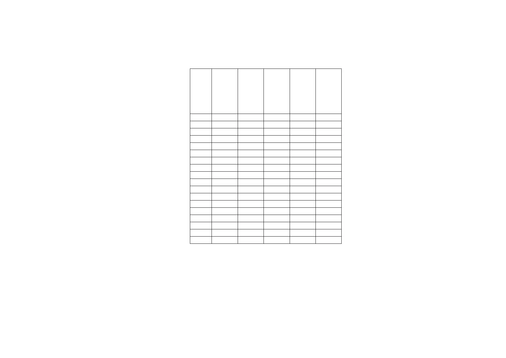
Each of the monitored drive components is represented by a bit in the 16-bit words, “Maintenance Warnings and “Maintenance Reset. Only the
bottom 6 bits of these words have any meaning, the other bits are ignored. The table below indicates which components are selected for a given
value.
Value
IO Option
Relays
Control Board
Relays
Main Fan
Auxilliary Fan
DC Link
Capacitors
(1)
xxx0
x
x
x
x
xxx1
x
x
x
xxx2
x
x
x
xxx3
x
x
xxx4
x
x
x
xxx5
x
x
xxx6
x
x
xxx7
x
xxx8
x
x
x
xxx9
x
x
xxxA
x
x
xxxB
x
xxxC
x
x
xxxD
x
xxxE
x
xxxF
xx0x
x
xx1x
(1) For future use. The DC Link Capacitors are not monitored in version x.16

Table of Contents

Other manuals for Parker AC30 series

Questions and Answers:

Question and Answer IconNeed help?

Do you have a question about the Parker AC30 series and is the answer not in the manual?

Parker AC30 series Specifications

General IconGeneral
Control ModesClosed-loop vector
FeedbackEncoder
Operating Temperature0 to 40°C (32 to 104°F) standard, -20 to 50°C (-4 to 122°F) with derating
ProtectionOvercurrent, Overvoltage, Undervoltage
CommunicationRS485

Related product manuals