Annexes
R&S
®
ZNL/ZNLE
1110User Manual 1178.5966.02 ─ 20
5. Pass the Windows User Account Control dialog. As a standard Windows user, you
have to enter an administrator name and password. Select "Yes" to proceed.
6. If requested by the uninstaller, perform a reboot.
After a possible reboot of the instrument, a new firmware can be installed by exe-
cuting its installer.
14.2 Interfaces and connectors
This chapter provides a detailed description of the rear panel connectors of the
R&S ZNL/ZNLE. An overview of the available front and rear panel is given in the Get-
ting Started guide (see Chapter 4.2, "Instrument tour", on page 38).
14.2.1 Rear panel connectors
The rear panel of the R&S ZNL/ZNLE provides various connectors for external devices
and control signals.
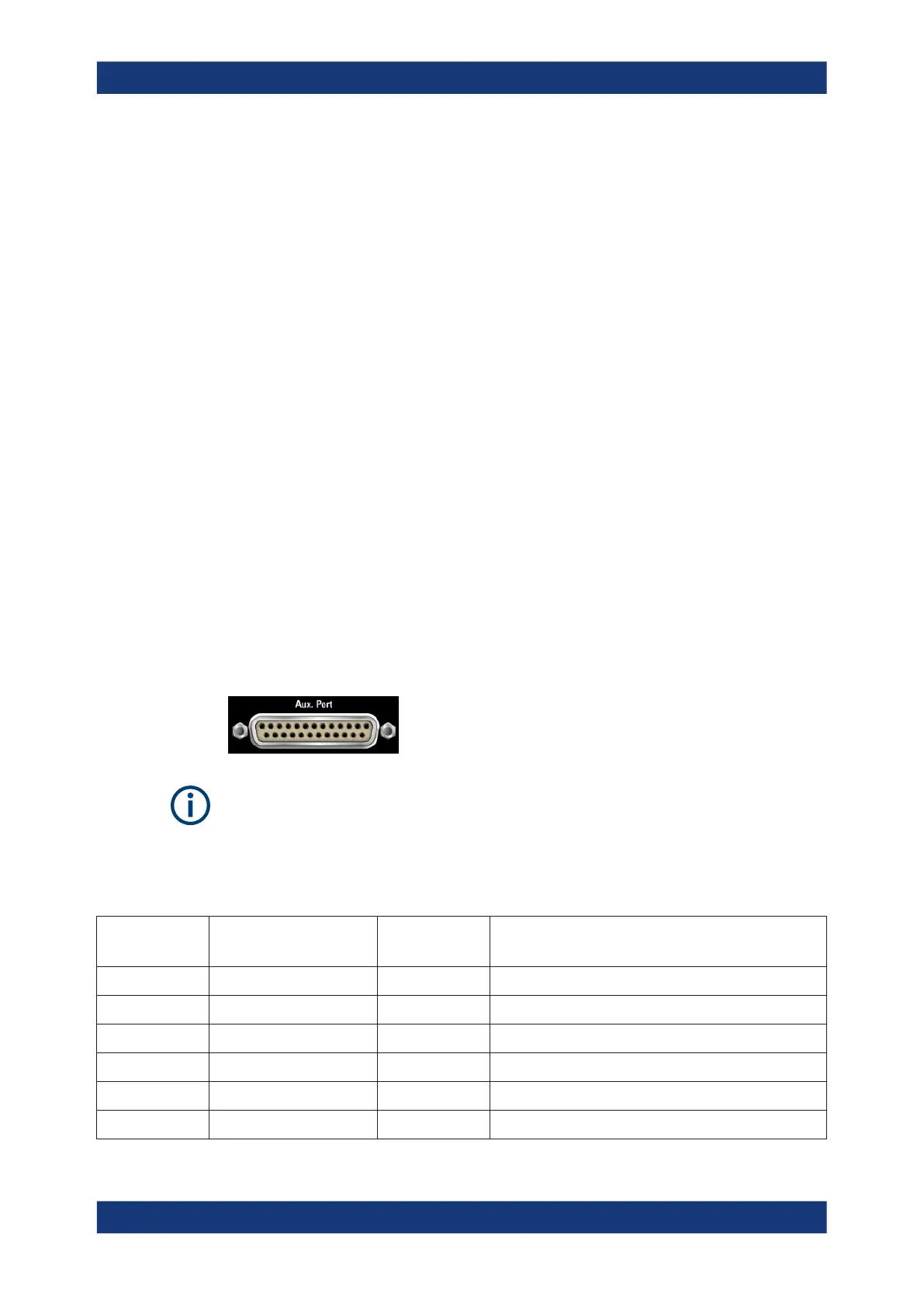
14.2.1.1 Aux. Port
25-pole D-Sub connector used as an input and output for low-voltage (3.3 V) TTL con-
trol signals. Some of the lines can be configured (see CONTrol commands and OUT-
Put commands).
The Aux. Port connector is part of option R&S FPL1-B5 "Additional Interfaces". This
option is not available for the R&S ZNLE.
To use the Aux. Port as VNA User Port (see table below) this has to be selected in the
"Add. Interfaces" tab of the "System Configuration" dialog.
Table 14-1: VNA User Port: Pole Assignment
Pin No. Name Input (I) or
Output (O)
Function
1 AGND - Ground
2 UC_EXT_TRG_IN I External trigger 1 input, 5 V tolerant *)
3 AGND - Ground
4 UC_BUSY O Hardware measurement time
5 AGND - Ground
6 READY FOR TRIGGER O Measurement completed, ready for new trigger
Interfaces and connectors

 Loading...


