VNA GUI reference
R&S
®
ZNL/ZNLE
371User Manual 1178.5966.02 ─ 20
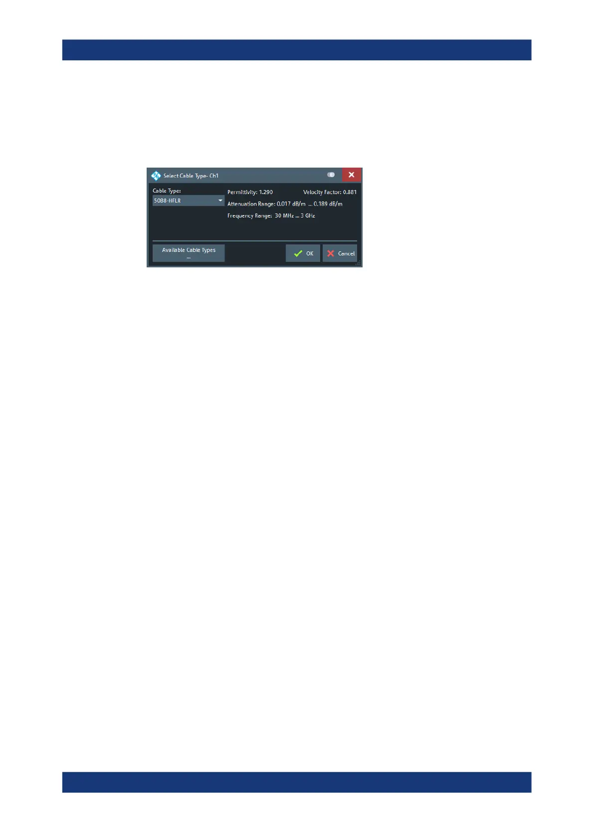
Cable Type...
Opens a dialog that allows to select a preconfigured cable type to be used for the cal-
culation of the Distance to Fault traces on the active channel. A cable type is defined
by its relative permittivity (or its velocity factor), and a frequency-dependent attenuation
table.
Select "Available Cable Types..." to access the list of predefined and user-defined
cable types (see Chapter 10.6.7.2, "Available Cable Types... dialog", on page 372).
Remote command:
CALCulate<Chn>:TRANsform:DTFault:SELect
Start Cal Unit... (P2) Refl OSM / Start Cal... (P2) Refl OSM
Sets up and runs the "Calibration Unit"/"Calibration Setting" wizard to perform a full
one-port calibration at physical port 2 (only port 2 enabled and calibration type "Refl
OSM" preselected).
The calibration serves several purposes:
●
Adjust the reference plane (distance zero).
●
Normalize the trace (total reflection of the signal corresponds to a 0 dB peak).
●
Avoid spurious effects, e.g. peaks on the impulse response trace that are not due
to a fault.
For descriptions of the calibration wizards and the corresponding remote commands,
see Calibration Unit wizard and Calibration Setting wizard.
Note: Make sure to select a sufficient number of sweep points and a suitable fre-
quency span before you start the calibration. Otherwise the measurement can yield
inaccurate results.
Use Auto Number of Points to let the firmware assist you.
Fault Limit Check
Enables/disables checking the current "Distance to Fault" trace for spikes above the
given Fault Limit (red line).
The fault limit is defined relative to the 0 dB-line in the test diagram, i.e. the peak
response value for total reflection after proper calibration.
Trace softtool

 Loading...


