R&S
®
ZVA / R&S
®
ZVB / R&S
®
ZVT Programming Examples
Basic Tasks
Operating Manual 1145.1084.12 – 30 1085
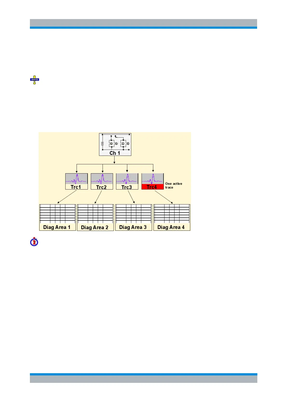
Handling of Channels, Traces and Diagram Areas
The following examples show you how to perform basic tasks related to channel and trace definition and
to the display of traces in diagram areas.
All example programs in this section have been developed and tested by means of the GPIB Explorer
provided with the network analyzer. No extra programming environment is needed.
Several Traces with Equal Channel Settings
Programming task: Create up to four different traces with equal channel settings, assign the four 2-port
standard S-parameters to the traces and display them in up to four diagram areas.
Important remote control features for this program example
The following command sequence illustrates the structure of the remote commands discussed in section
Basic Remote Control Concepts. In particular it shows that:
A trace can be created and handled without being displayed.
Traces are referenced by trace names. The active trace of a channel is often referenced by the
channel suffix.
Diagram areas are referenced by a window suffix <Wnd>. An additional suffix <WndTr> in the
DISPlay:WINDow<Wnd>:TRACe<WndTr>... commands numbers the different traces in a
diagram area.
In remote control, it is possible to display the same trace in several diagram areas.
The analyzer provides several commands allowing a smooth transition between remote and
manual control.
//
// 1. One channel, two traces, one diagram area
// Reset the instrument, creating the default trace Trc1 in channel 1.