R&S
®
ZVA / R&S
®
ZVB / R&S
®
ZVT System Overview
Calibration Overview
Operating Manual 1145.1084.12 – 30 52
a test fixture), it is possible to shift the calibration plane using length offset parameters.
Differential and common mode parameters can be evaluated with a single test setup.
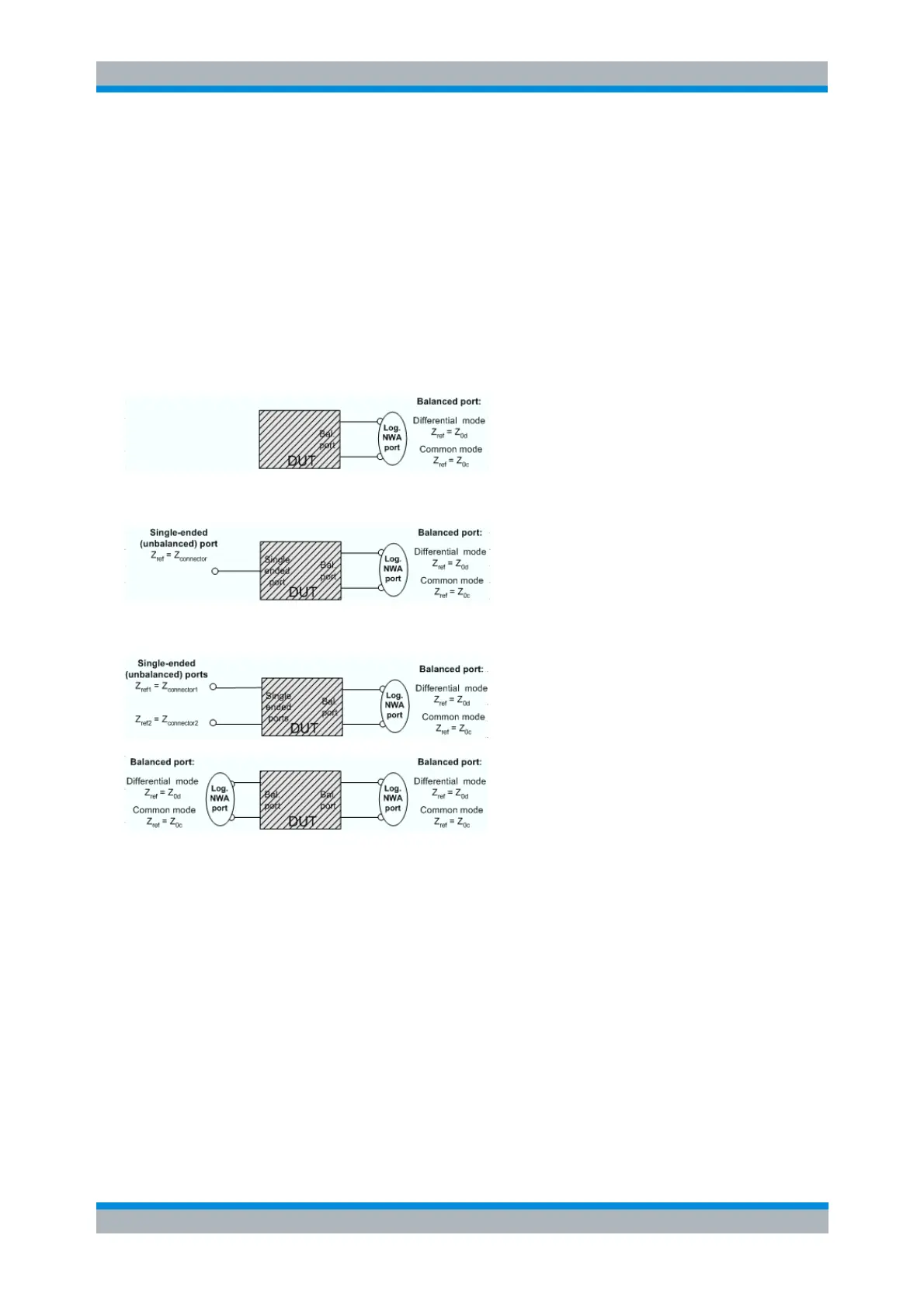
Balanced Port Configurations
Defining a logical ports requires two physical analyzer ports. The ports of an analyzer are equivalent and
can be freely combined. Moreover, it is possible to assign arbitrary, independent reference impedance
values to each unbalanced port and to the differential and common mode of each logical port. The
following types of balanced devices can be measured with 2-port, 3-port and 4-port analyzers:
2-port analyzers: Reflection measurements on 1 balanced port
3-port analyzers: Reflection and transmission measurements on 1 balanced port
4-port analyzers: Reflection and transmission measurements on 1 or 2 balanced ports
A balanced port configuration is defined by simply selecting the pairs of physical ports that are combined
to form balanced ports and defining the two reference impedances for the differential and common mode
at each balanced port. All this is done in a single dialog; refer to the help system for details and
measurement examples. The most commonly used balanced port configurations and impedances are
predefined and can be selected in the Measurement Wizard.
Depending on the test setup, the analyzer provides different types of mixed mode parameters; refer to the
following sections for details.
Calibration Overview
Calibration or "system error correction" is the process of eliminating systematic, reproducible errors from
the measurement results (S-parameters and derived quantities; see Data Flow). The process involves the
following stages:
1. A set of calibration standards is selected and measured over the required sweep range. For many