R&S
®
ZVA / R&S
®
ZVB / R&S
®
ZVT System Overview
Screen Elements
Operating Manual 1145.1084.12 – 30 27
Display Elements in the Diagram Area
The central part of the screen is occupied by one or several diagram areas.
Diagram Areas
A diagram area is a rectangular portion of the screen used to display traces. Diagram areas are arranged
in windows; they are independent of trace and channel settings. A diagram area can contain a practically
unlimited number of traces, assigned to different channels (overlay mode).
Diagram areas are controlled and configured by means of the functions in the Display menu and the
following additional settings:
The settings in the Window menu arrange several windows containing one or more diagram areas
within the entire screen. Each window corresponds to a setup. Only one setup can be active at a
time, and only the traces of the active setup are updated by the current measurements.
Various settings to assign traces to diagram areas are provided in the Trace – Traces submenu.
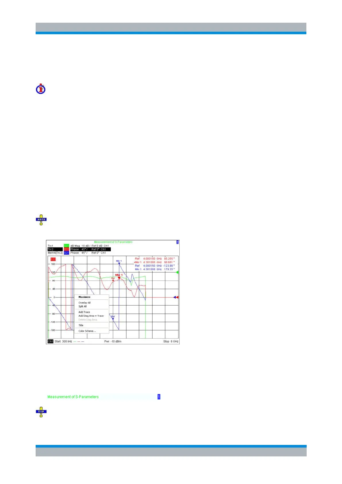
Diagram areas may contain:
Measurement results, in particular the traces and marker values
An indication of the basic channel and trace settings
Context menus providing settings related to the current screen
The examples in this section have been taken from Cartesian diagrams. All other diagram types
provide the same display elements.
Title
Across the top of the diagram area, an optional title describes the contents of the area. Different areas
within a setup are distinguished by area numbers in the upper right corner.
Use the context menu or the functions in the Display menu to display, hide or change the title and to
add and customize diagram areas.