R&S
®
ZVA / R&S
®
ZVB / R&S
®
ZVT Annexes
Interfaces and Connectors
Operating Manual 1145.1084.12 – 30 1130
Attention!
The maximum input levels at all test ports according to the front panel labeling or the
data sheet must not be exceeded.
In addition, the maximum input voltages of the other input connectors at the front and
rear panel must not be exceeded.
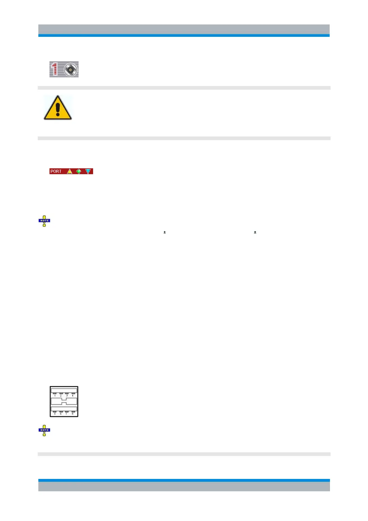
The three LEDs above each test port indicate the connector state:
The amber LED is on while the connector is used as a source port.
The green LED is on while the connector is used as a bidirectional (source and receive) port.
The blue LED is on while the connector is used as a receive port.
It is recommended to use a torque wrench when screwing RF cables on the test port connectors.
Standard IEEE 287 specifies a torque of (1.5 0.2) Nm for N connectors, (0.9 0.1) Nm for the other
connector types.
USB Connector
Double Universal Serial Bus connector of type A (master USB), used to connect e.g a keyboard, mouse or
other pointing devices, the Calibration Unit (accessory R&S ZV-Z5x), a printer or an external storage
device (USB stick, CD-ROM drive etc.).
The USB connector can be used for data transfer from and to the analyzer, in particular to do the
following:
Store data files from the analyzer, e.g. store a setup to be used on another instrument or at a later
time.
Load data files, e.g. calibration kits, memory traces, setups.
Perform a firmware update.
To control external devices (e.g. power meters, generators) via USB connector, a VISA installation on the
network analyzer is required. Use the USB-to-IEC/IEEE Adapter (option R&S ZVAB-B44) to control
devices equipped with a GPIB interface.
The length of passive connecting USB cables should not exceed 1 m. The maximum current per USB
port is 500 mA.
See also EMI Suppression in chapter Preparing for Use.