R&S
®
ZVA / R&S
®
ZVB / R&S
®
ZVT Annexes
Interfaces and Connectors
Operating Manual 1145.1084.12 – 30 1131
R&S ZVAB-B44 on network analyzers with FMR6/7 and FMR9
The driver software of the USB-to-IEC/IEEE Adapter (option R&S ZVAB-B44) must be
installed on the network analyzer. On analyzers equipped with a CPU board FMR7/6 or
FMR9, this installation disables GPIB control from an external PC. A reinstallation of the
NWA firmware (e.g. in repair mode) will resolve the problem; see Firmware Update.
Ground Connector
Connector providing the ground of the analyzer's supply voltage.
Attention!
Electrostatic discharge (ESD) may cause damage to the electronic components of the
DUT and the analyzer. Use the wrist strap and cord supplied with the instrument to
connect yourself to the GND connector.
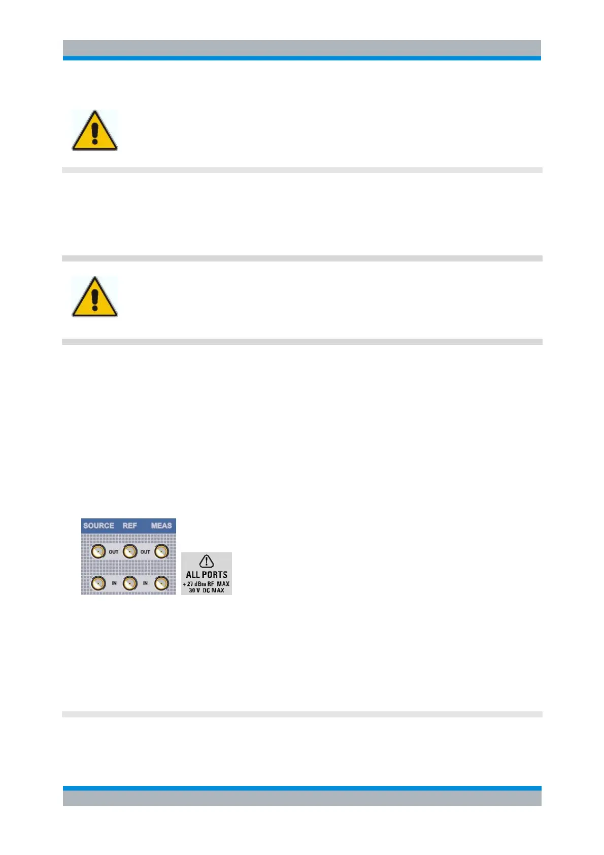
Direct Generator and Receiver Access
Option R&S ZVA<frequency>-B16, Direct Generator/Receiver Access, provides 3 pairs of SMA
connectors (or smaller connectors, for microwave analyzers) for each test port. <frequency> corresponds
to the network analyzer type. For detailed ordering information refer to the product brochure. See also
section Converter Control.
The connectors give direct access to various RF input and output signals. They can be used to insert
external components (e.g. external signal separating devices, power amplifiers, an extension unit etc.) into
the signal path in order to develop custom measurements, e.g. to test high power devices and extend the
dynamic range. If no external components are connected, each OUT/IN loop should be closed using a
jumper.
The SOURCE OUT signal comes from the internal RF signal source. The SOURCE IN signal
goes to the test port. A power amplifier can be inserted between SOURCE OUT and SOURCE IN
in order to boost the test port power.
The REF OUT signal comes from the coupler and provides the reference signal. The REF IN
signal goes to the receiver input for the reference signal.
The MEAS OUT signal comes from the coupler and provides the received (measured) signal. The
MEAS IN signal goes to the receiver input for the measured signal.