R&S
®
ZVA / R&S
®
ZVB / R&S
®
ZVT System Overview
Measured Quantities
Operating Manual 1145.1084.12 – 30 51
3. DUT with one balanced and one single-ended port.
4. DUT with two balanced ports or one balanced and two single-ended ports. Both device types are
fully characterized by 4x4 mixed mode S-matrices.
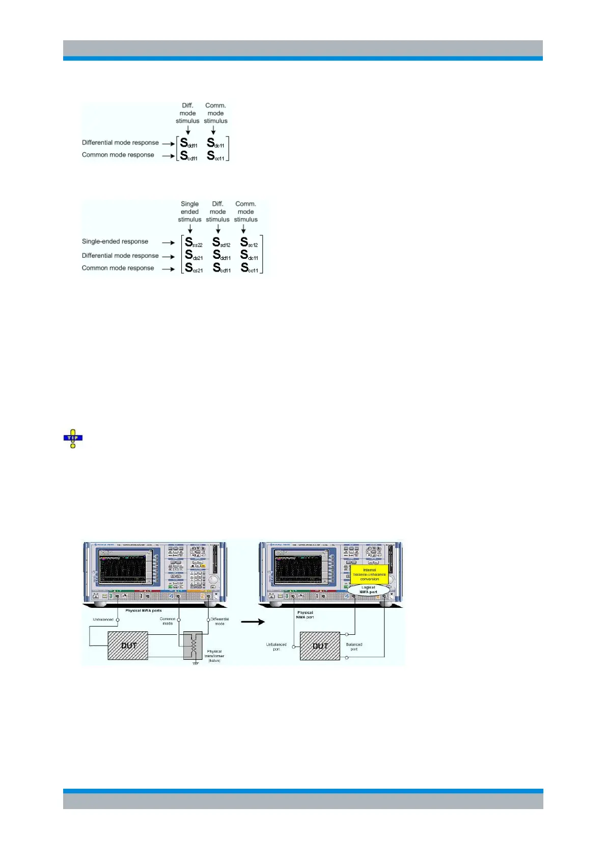
Unbalance-Balance Conversion
Unbalance-balance conversion is the simulation of one or more unbalance-balance transformers (baluns)
integrated in the measurement circuit in order to convert the DUT ports from an unbalanced state into a
balanced state and virtually separate the differential and common mode signals. The analyzer measures
the unbalanced state but converts the results and calculates mixed mode parameters, e.g. mixed mode S-
parameters. No physical transformer is needed.
With option R&S ZVA-K6, True Differential Mode, the analyzer can generate balanced waves at
arbitrary reference planes in the test setup and determine balanced results such as S-parameters, wave
quantities and ratios. The true differential mode also provides two additional sweep types, the amplitude
imbalance and phase imbalance sweeps. What is said below is valid for both the simulated balanced
mode and the true differential mode.
To perform balanced measurements, a pair of physical analyzer ports is combined to form a logical port.
The balanced port of the DUT is directly connected to the analyzer ports
Unbalance-balance conversion avoids the disadvantages of real transformers:
There is no need to fabricate test fixtures with integrated baluns for each type of DUT.
The measurement is not impaired by the non-ideal characteristics of the balun (e.g. error
tolerances, limited frequency range).
Calibration can be performed at the DUT's ports. If necessary (e.g. to compensate for the effect of