R&S
®
ZVA / R&S
®
ZVB / R&S
®
ZVT Annexes
Interfaces and Connectors
Operating Manual 1145.1084.12 – 30 1132
Attention!
The maximum RF input levels at all SMA inputs according to the front panel labeling or
the data sheet must not be exceeded.
In addition, it is important that the signal fed in at the SMA inputs contains no DC offset,
as this may impair the measurements and even cause damage to the instrument.
Rear Panel Connectors
The rear panel of the analyzer provides various connectors for external devices and control signals.
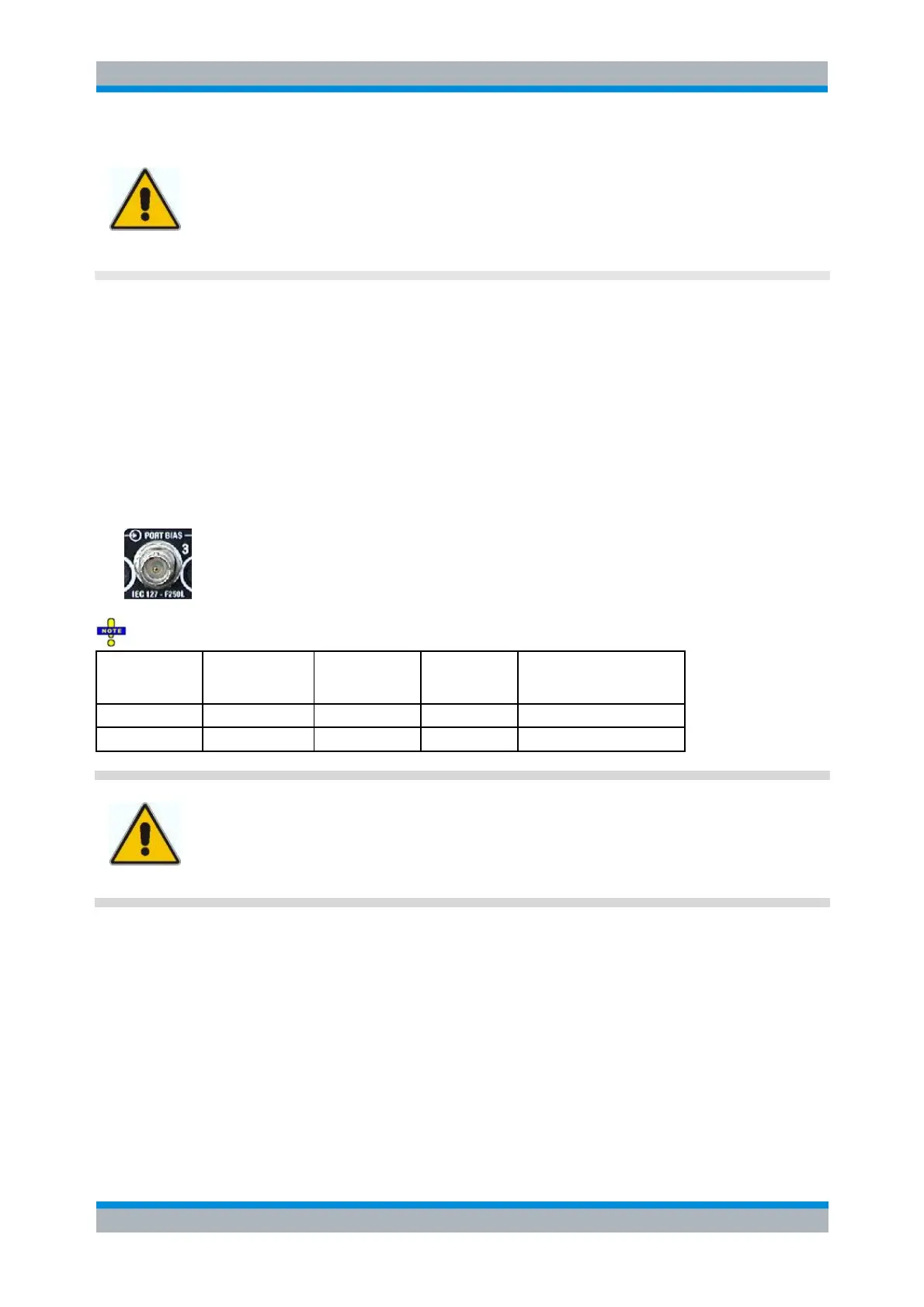
PORT BIAS
Coaxial BNC connectors used to apply an external DC voltage (bias) to the test ports. The PORT BIAS
connectors are numbered 1 to 4 (for four-port analyzers). The internal equivalent circuit is shown in
section Direct Generator and Receiver Access.
Each PORT BIAS input is protected by an exchangeable fuse.
Input (I) or
Output (O) or
Bidirectional (B)
DC input for test port 1/2/3/4
Attention!
Use double shielded cables at the BNC rear panel connectors and match signal with 50
Ω in order to comply with EMC directives!
See also EMI Suppression in chapter Preparing for Use.
AUX
Coaxial bidirectional auxiliary connector that can be wired as needed. The AUX connector is not fitted on
standard instruments.
LAN1 / LAN 2
8-pin connector RJ-45 used to connect the analyzer to a Local Area Network (LAN). The pin assignment
of the RF-45 connector supports category 6 / 7 UTP/STP (Unshielded/Shielded Twisted Pair) cables.