R&S
®
ZVA / R&S
®
ZVB / R&S
®
ZVT Measurement Examples
Calibration
Operating Manual 1145.1084.12 – 30 79
You can use the sliding match instead of the fixed match in order to improve the accuracy of the
system error correction. Both standards cover the same frequency range.
You can check the calibration by measuring a standard that was not used during the system error
correction. If you use the sliding match for system error correction, you can use the fixed match to check
the calibration. Note that this check is incomplete (e.g. the transmission is not verified when using a one-
port standard like a fixed match).
UOSM Calibration
UOSM calibration uses an unknown through and yields two solutions related to different transmission
phase values. The two solutions differ by 180 deg - only one solution is valid. Any two-port network whose
S-parameters fulfill the reciprocity condition S
21
=S
12
can be used as an unknown through (e.g. a
waveguide bend).
Within a coaxial system the analyzer selects the correct solution automatically. This is not possible in a
waveguide system because the delay time is frequency-dependent (dispersive propagation). The valid
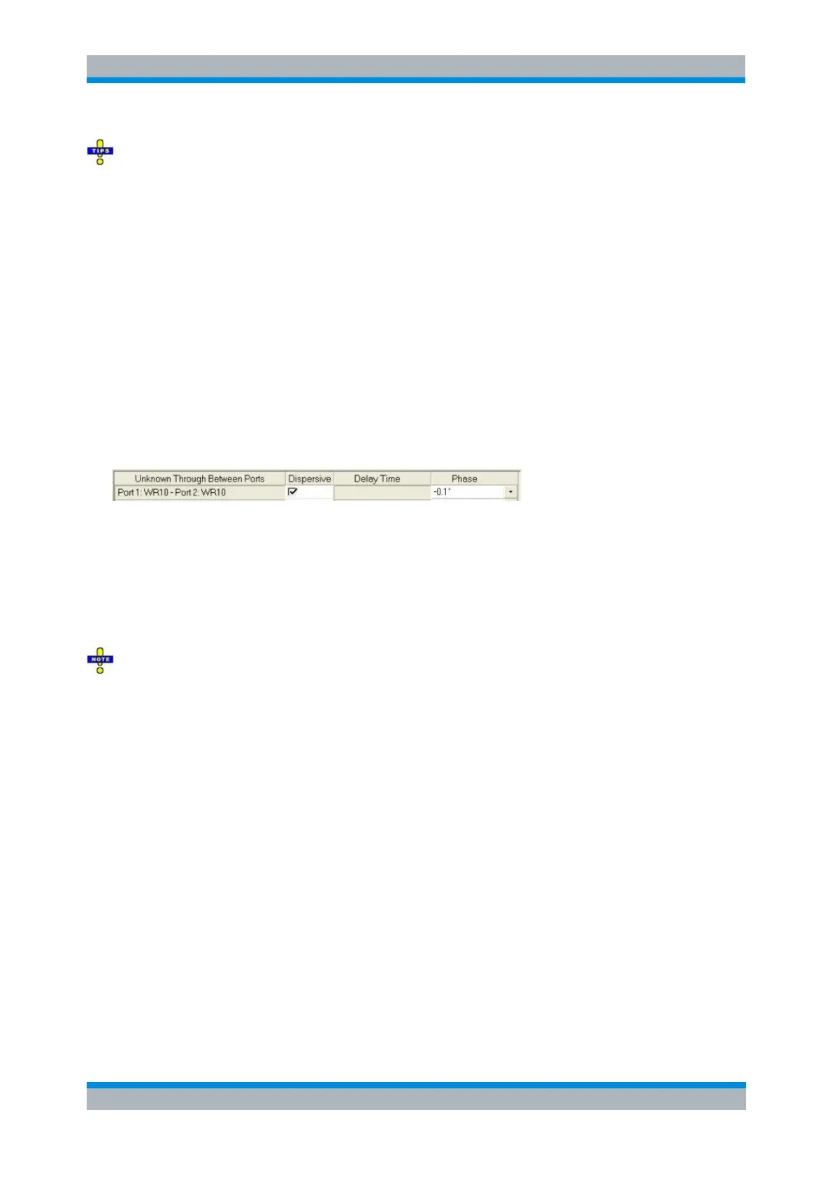
solution has to be selected manually. For this purpose the following dialog opens during calculation of the
system error correction data (see step 8 above):
Check “Dispersive” and select the right solution from the "Phase" drop-down list.
Waveguide Calibration using Kit R&S ZV-WR03
The waveguide calibration kit R&S ZV-WR03 allows to calibrate network analyzers for test setups
involving frequency converters, in particular R&S ZVA-Z325.
Accuracy considerations
Thermal fluctuations cause linear expansion of the waveguide components and result in phase
drift. An environment with a stable temperature within the range stated in the data sheet is a
prerequisite for accurate measurements.
A power calibration must be performed previous to system error correction. Refer to the
documentation of your frequency converter for instructions.
If you readjust the output power of the frequency converter (using the knurled knob at the top of
the converter) an already performed system error correction is no longer valid. For that reason
adjust the output power of the frequency converter before system error correction.
TRL Calibration
The following example reports a TRL calibration for a four port R&S ZVA analyzer which is connected to
two frequency converters; see Connecting the Converter. It is suitable for transmission and reflection
measurements on two-port waveguide DUTs in the frequency range of the converters.
The calibration procedure using the analyzer’s “Calibration Wizard” is straightforward (for details refer to
the analyzer help system, section “Guided Calibration”):
1. Activate the Frequency Converter Mode (“System” > “System Config…” > “Frequency Converter”)
and connect the two converters.