The noise figure calibration is invalid, e.g. because:
The gain and noise measurement method was changed from "Sequential" to "Simultaneous" or vice versa (see
Define Noise Figure Measurement dialog).
The IF Gain settings were changed.
Length offset parameters: Definition
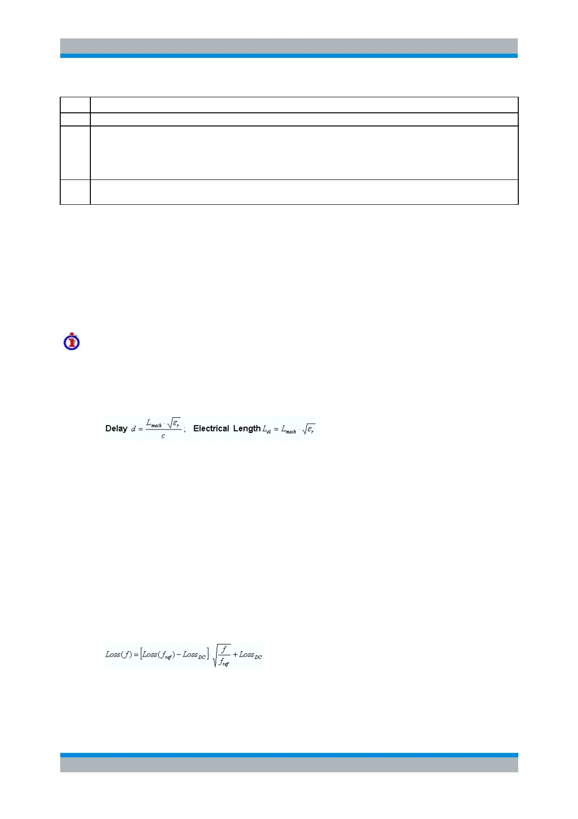
The Delay is the propagation time of a wave traveling through the transmission line. The Electrical
Length is equal to the Delay times the speed of light in the vacuum and is a measure for the length
of transmission line between the standard and the actual calibration plane. For a line with
permittivity ε
r
and mechanical length L
mech
the delay and the electrical length are calculated as
follows:
Electrical Length, Mechanical Length or Delay are coupled parameters. When one of them is
changed, the other two follow.
For a non-dispersive DUT, the delay defined above is constant over the considered frequency
range and equal to the negative derivative of the phase response with respect to the frequency
(see mathematical relations). The length offset parameters compensate for a constant delay, which
is equivalent to a linear phase response.
If a dispersive connector type (i.e. a waveguide; see Offset Model dialog) is assigned to a test port
that is related to a particular quantity, then the phase of the quantity is calculated taking dispersion
effects into account.
Loss parameters: Definition
The loss L is the attenuation of a wave traveling through the offset transmission line. In logarithmic
representation, the loss can be modeled as the sum of a constant and a frequency-dependent part.
The frequency dependence is essentially due to the skin effect; the total loss can be approximated
by an expression of the following form:
The DC loss Loss
DC
, the reference frequency f
ref
, and the loss at the reference frequency Loss(f
ref
)
are empirical parameters for the transmission lines connected to each port which can be entered
into any of the dialogs in the Offset menu (see figure below). For a lossless transmission line,