R&S
®
ZVA / R&S
®
ZVB / R&S
®
ZVT GUI Reference
Channel Menu
Operating Manual 1145.1084.12 – 30 426
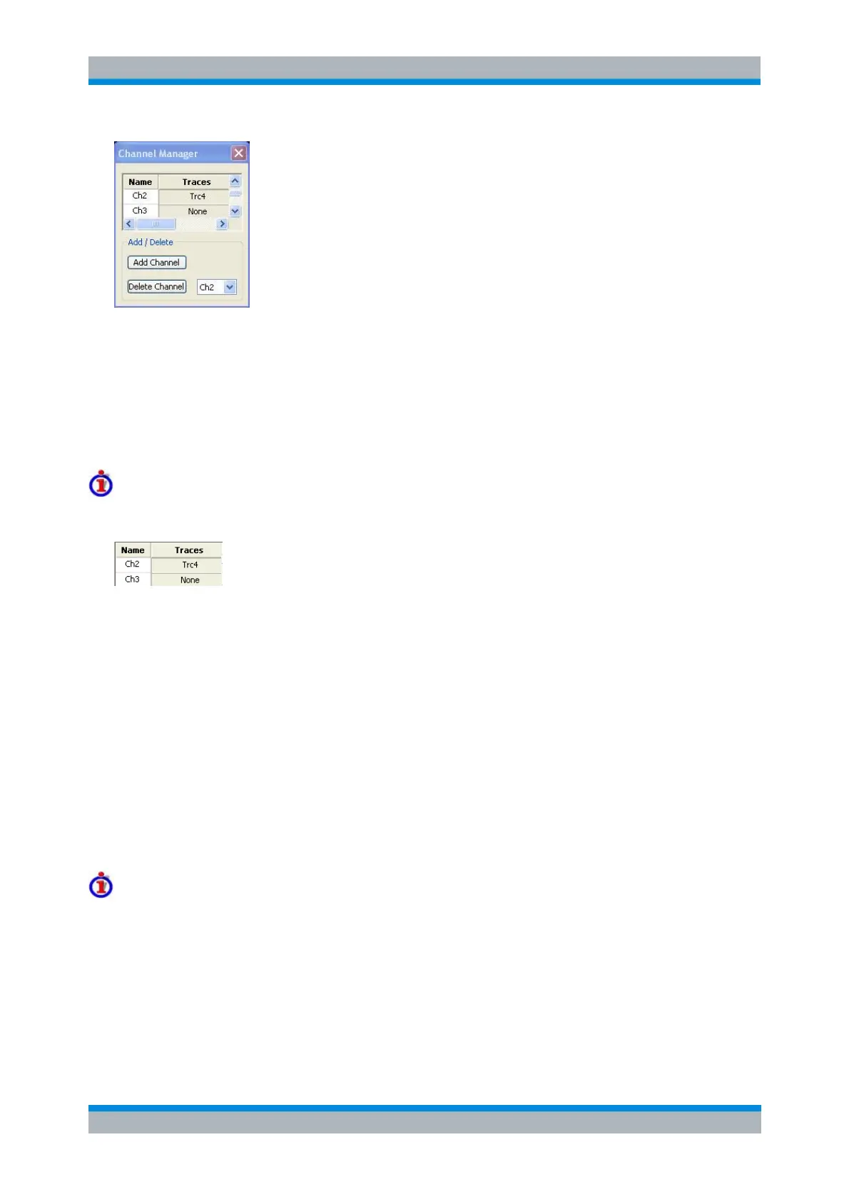
All existing channels of the current setup are listed in a table; see below. Below the table the Trace
Manager provides the following buttons:
Add Channel adds a new channel to the list. The new channel is named Ch<n>, where <n> is the
largest of all existing channel numbers plus one.
Delete Channel deletes the channel selected in the drop-down menu. This button is disabled if the
setup contains only one channel: In manual control, each setup must contain at least one diagram
area with one channel and one trace.
Columns in the Channel Manager table
The channel table contains several editable (white) or non-editable (gray) columns.
Channel indicates the current channel name. The default names for new channels are Ch<n>
where <n> is a current number.
Traces indicates the names of all traces assigned to the channel.
CONFigure:CHANnel<Ch>:CATalog?
CONFigure:CHANnel<Ch>:NAME
CONFigure:CHANnel<Ch>:NAME:ID?
CONFigure:CHANnel<Ch>[:STATe]
Channel - Calibration
The Calibration menu provides all functions that are necessary to perform a system error correction
(calibration) or a power calibration.
For an introduction to calibration and calibration types refer to section Calibration Overview in the
System Overview chapter. See also the Data Flow overview in the System Overview chapter.