R&S
®
ZVA / R&S
®
ZVB / R&S
®
ZVT Annexes
Universal Interface (R&S ZVA and R&S ZVB)
Operating Manual 1145.1084.12 – 30 1151
and specify whether this state will change to "Low" when the Input 1 signal goes to "Low". This
mechanism provides either static output signals or output signals which are controlled by Input 1.
The Index and Ready for Trigger signals can be routed to pins 20 and 21 of the Universal
Interface connector, where they replace the PORT B6 and PORT B7 input/output signals. See
section Data Ports below.
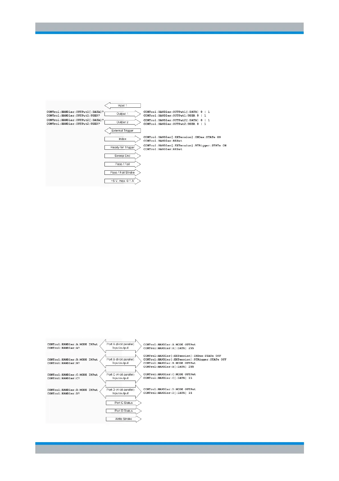
Control signals and power supply
Data Ports
In addition to the control signals, the Universal Interface provides four bi-directional data ports A, B, C, D.
The data ports must be configured explicitly using SCPI commands; they are not controlled by the
measurement.
With an output data port you can configure the part handler or other devices used in testing from
the network analyzer.
With an input data port you can configure the network analyzer using external signals and an
appropriate control program.
Device configurations via data port signals are usually performed in a preliminary stage, prior to the actual
measurement sequence. If the Index and Ready for Trigger signals are enabled at this stage (see section
Control Signals), they replace the PORT B6 and PORT B7 signals. Port B can still be used as a 6-bit
parallel input/output port.