R&S
®
ZVA / R&S
®
ZVB / R&S
®
ZVT Annexes
Interfaces and Connectors
Operating Manual 1145.1084.12 – 30 1137
EXT TRIGGER
Coaxial BNC connector used as an input for a low-voltage (3.3 V) TTL external trigger signal.
*) Note: Feeding in the external trigger signal at pin 2 of the D-Sub connector USER CONTROL is
equivalent. Both input connectors must not be used simultaneously, because this can cause malfunctions
of the analyzer.
Input (I) or
Output (O) or
Bidirectional (B)
Use double shielded cables at the BNC rear panel connectors and match signal with 50 Ω in order to
comply with EMC directives!
See also EMI Suppression in chapter Preparing for Use.
LAN Interface
The analyzer provides two LAN connectors for direct connection to a Local Area Network. Remote control
via LAN requires a VISA installation but no additional hardware at the controller. VISA provides the TCPIP
interface type and several protocol types to communicate with LAN-connected devices. The analyzer
supports the following protocols
VXI-11
RSIB
VXI-11 Protocol
The VXI–11 standard is based on the RPC protocol which in turn relies on TCP/IP as the
network/transport layer. The TCP/IP network protocol and the associated network services are pre-
configured. TCP/IP ensures connection–oriented communication, where the order of the exchanged
messages is adhered to and interrupted links are identified. With this protocol, messages cannot be lost.
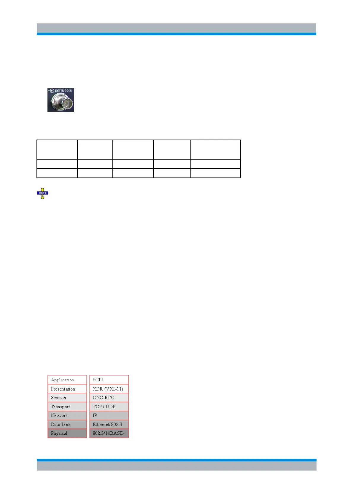
Remote control of an instrument via a network is based on standardized protocols which follow the OSI
reference model (see Fig. below).