R&S
®
ZVA / R&S
®
ZVB / R&S
®
ZVT Annexes
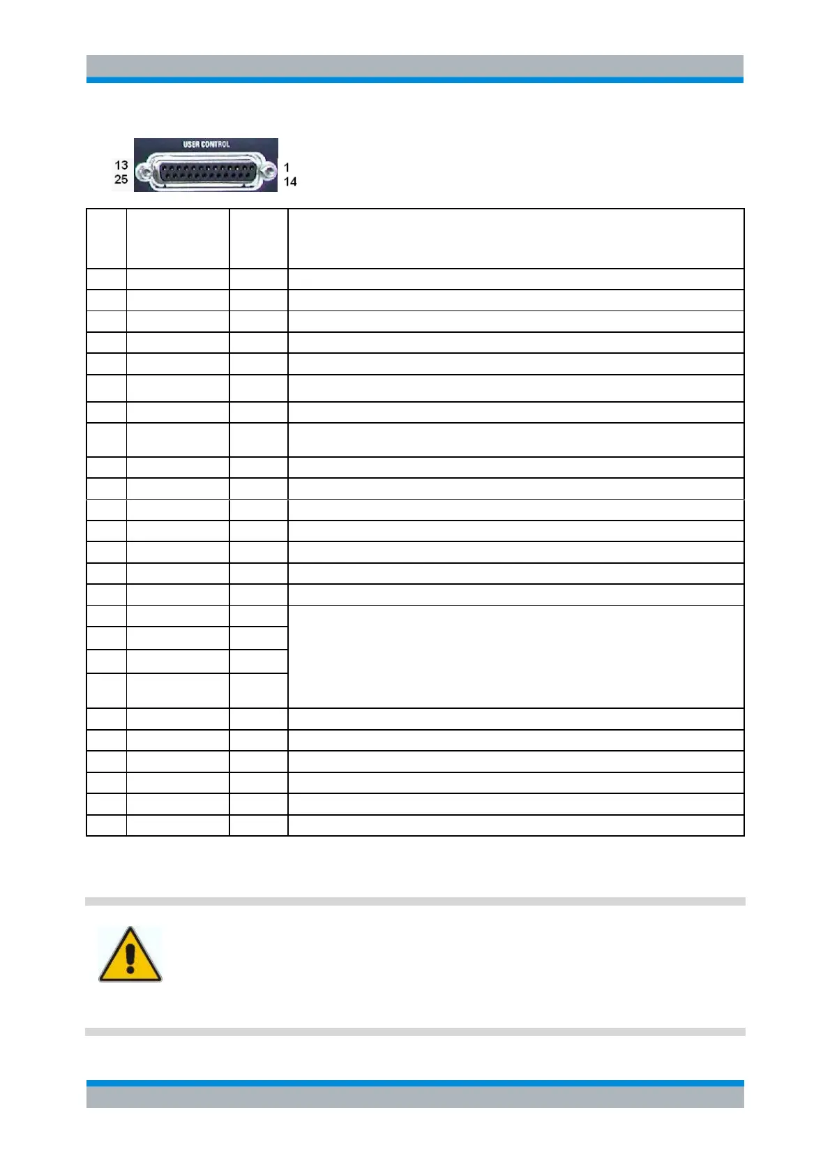
Interfaces and Connectors
Operating Manual 1145.1084.12 – 30 1136
External trigger signal *)
Measurement running, configurable signal (see Define Busy Signal)
Measurement terminated, ready for trigger (not available for pulsed measurements)
Channel-specific bit 0;
see CONTrol:AUXiliary:C[:DATA] and OUTPut<Ch>:UPORt[:VALue]
Pass/fail result of limit check TTL Out Pass 1
Pass/fail result of limit check TTL Out Pass 2
Multi-purpose, with the following order of precedence:
1. Segment Bits
2. Additional Channel Bits 4 to 7
3. Diplexer control for R&S ZVA110 (default for this instrument)
4. Drive Ports, i.e. DRIVE PORT i indicates test port i is source port (default for
instruments other than R&S ZVA110)
Control signal for external generator
Handshake signal from external generator
*) Note: Feeding in the external trigger signal via the BNC connector EXT TRIGGER is equivalent.
Both input connectors must not be used simultaneously, because this can cause malfunctions of the
analyzer.
Important note:
Use only well shielded cables or disconnect the input pins of the USER CONTROL
connector in order to avoid spurious input signals which may cause undesirable events.
This is of particular importance for the external trigger input (pin no. 2) if the EXT
TRIGGER input is used.