R&S
®
ZVA / R&S
®
ZVB / R&S
®
ZVT GUI Reference
Channel Menu
Operating Manual 1145.1084.12 – 30 261
segment numbers (#) of all segments after the new segment are adapted.
The new segment ranges from the Stop value of the previously active segment to the maximum
frequency of the analyzer. If the previously active segment ranges up to the maximum frequency,
the new segment is created with minimum width. The analyzer places no restriction on the
number of segments in a sweep range.
Delete removes the selected segment from the list.
Delete All clears the entire segment list so it is possible to define or load a new segmented sweep
range.
[SENSe<Chn>:]SEGMent<Seg>:INSert
[SENSe<Chn>:]SEGMent<Seg>:DEFine
[SENSe<Chn>:]SEGMent<Seg>:DELete
[SENSe<Chn>:]SEGMent<Seg>:DELete:ALL
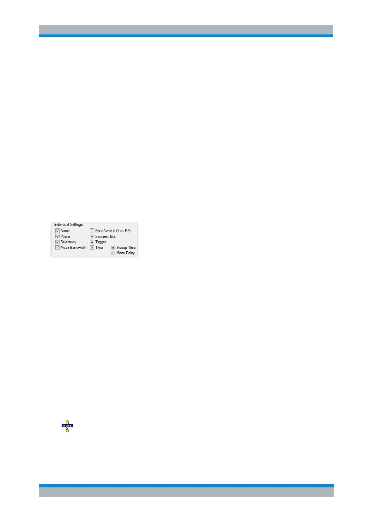
Individual Segment Settings
The options in the Individual Segment Settings panel can be used to vary the channel settings of every
individual segment in the list.
The first sweep segment is created with the channel settings defined for unsegmented sweep types.
When any further sweep segment created, it uses the channel settings of the previously active segment.
Each selected (checked) option adds a column to the segment list.
Name adds a column to assign a name to each segment. A segment name is a string that may
contain letters, numbers and special characters.
Power defines the internal source Power for each individual sweep segment.
Meas Bandwidth defines the Meas Bandwidth for each individual sweep segment.
Selectivity defines the Selectivity of the IF filter used for each sweep segment.
Spur Avoid defines whether the analyzer measures the segment with a local oscillator frequency
LO below or above the RF input frequency. The parameter replaces the Spurious Avoidance
settings for a particular segment.
Segment Bits
Enables the definition of a segment-dependent four-bit binary value to control four independent
output signals at the USER CONTROL connector (pins 16 to 19). The output signals are 3.3 V
TTL signals which can be used to differentiate between up to 16 independent analyzer states. For
an application example refer to the detailed remote control description. Setting the segment bits
does not change the analyzer state.
If active, the Segment Bit settings will take precedence over the (additional) channel bit
settings for pins 16 to 19 that can be performed in the System Configuration dialog.
Trigger
Enables the Trig column in the Define Segments table which in turn allows to deactivate triggering