R&S
®
ZVA / R&S
®
ZVB / R&S
®
ZVT Measurement Examples
Trace Evaluation
Operating Manual 1145.1084.12 – 30 81
the fixed match in order to improve the accuracy of the system error correction. Both standards cover the
same frequency range.
You can check the calibration by measuring a standard that was not used during the system error
correction (e.g. the fixed match to check a TRL calibration). Note that this check is incomplete (e.g. the
transmission is not verified when using a one-port standard like a fixed match).
UOSM Calibration
UOSM calibration uses an unknown through and yields two solutions related to different transmission
phase values. The two solutions differ by 180 deg - only one solution is valid. Any two-port network whose
S-parameters fulfill the reciprocity condition S
21
=S
12
can be used as an unknown through (e.g. a
waveguide bend).
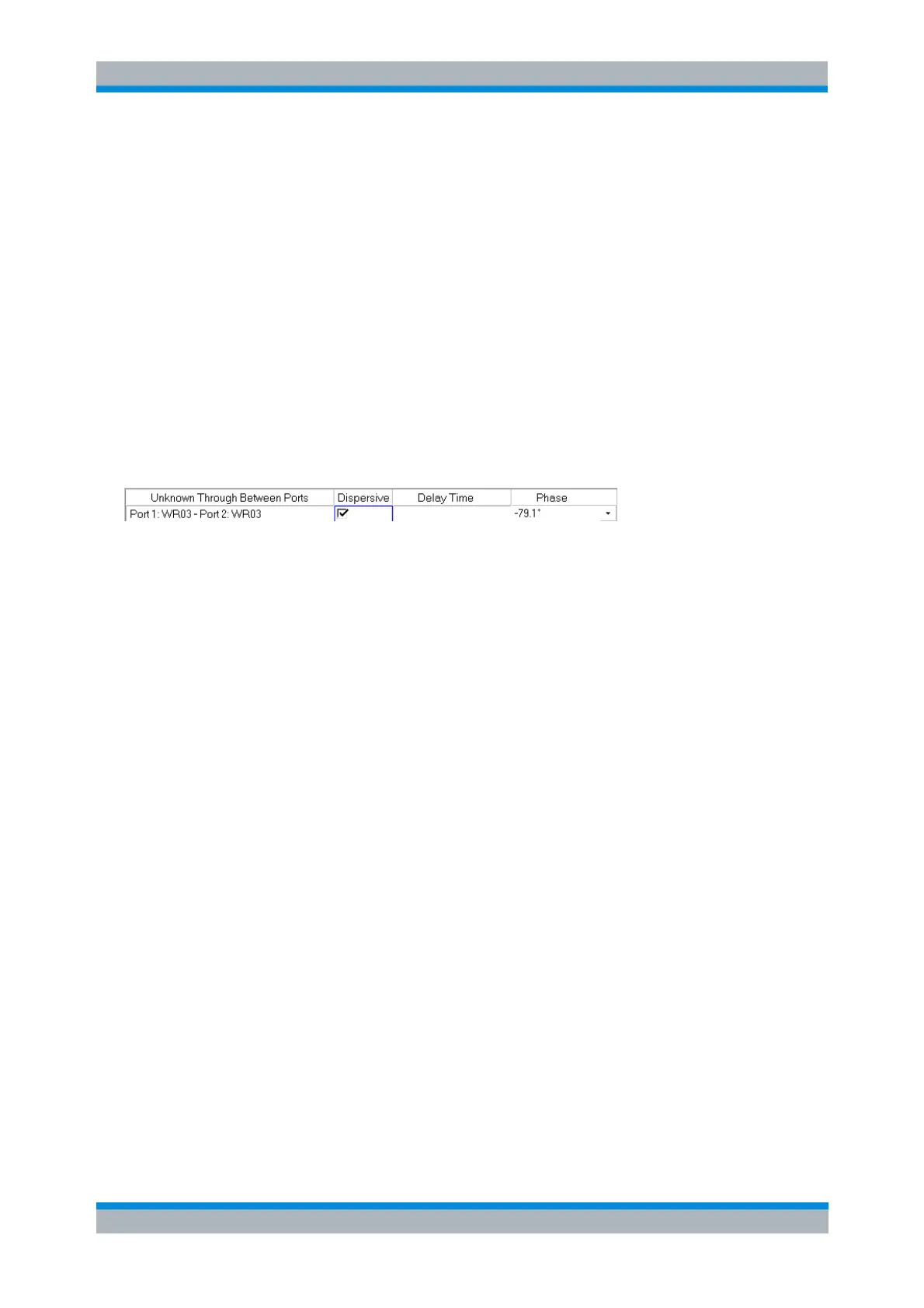
Within a coaxial system the analyzer selects the correct solution automatically. This is not possible in a
waveguide system because the delay time is frequency-dependent (dispersive propagation). The valid
solution has to be selected manually. For this purpose the following dialog opens during calculation of the
system error correction data (see step 8 above):
Check “Dispersive” and select the right solution from the "Phase" drop-down list.
Trace Evaluation
Operations on Traces
Trace Mathematics
Mathematical relations between traces can be used to compare different traces, correct traces, re-design
measurements or create new measurements. Trace mathematics is always based on linear, complex
trace data (irrespective of the actual trace format).
To compare two traces displayed in dB Mag format...
Suppose you have created a channel no. 1 with two traces named Trc1 and Mem2[Trc1] and that you
wish to compare the magnitudes of the two traces.
1. Display the traces in a common diagram area using the default trace format dB Mag (see
example of two traces with approx. constant magnitude difference).