R&S
®
ZVA / R&S
®
ZVB / R&S
®
ZVT Annexes
Interfaces and Connectors
Operating Manual 1145.1084.12 – 30 1129
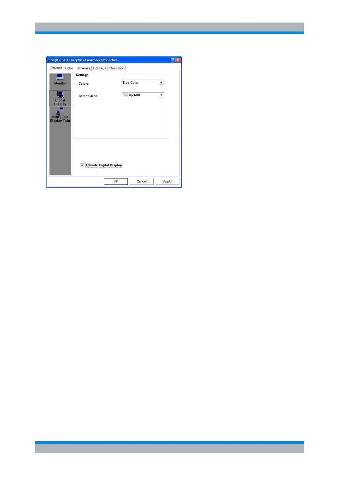
2. Select the Activate Digital Display check box and press OK. The external monitor is turned off and
the analyzer's internal LCD display is reactivated.
Interfaces and Connectors
This chapter provides a detailed description of the hardware interfaces and connectors of the instrument.
For a graphical overview of the front panel and rear panel connectors and their use refer to chapter
Preparing for Use:
Front Panel Connectors
The test ports and various additional connectors are located on the front panel of the analyzer.
Test Ports
N-connectors (or smaller connectors for microwave analyzer types), numbered 1, 2 ... The test ports serve
as outputs for the RF stimulus signal and as inputs for the measured RF signals from the DUT (response
signals).
With a single test port, it is possible to generate a stimulus signal and measure the response
signal in reflection.
With 2, 3 or 4 test ports, it is possible to perform full two-port, 3-port or 4-port measurements; see
S-Parameters section in chapter System Overview. Note that pairs of test ports (1and 2, 3 and 4)
are supplied by a common generatorCoupled Test Ports(exceptions: R&S ZVA24 with 4 ports and
4 sources, R&S ZVA40 with 4 ports and 4 sources, R&S ZVA67).
Each test port may be complemented by three pairs of additional connectors used to test high
power devices and extend the dynamic range, see section Direct Generator and Receiver Access
below.