R&S
®
ZVA / R&S
®
ZVB / R&S
®
ZVT GUI Reference
Channel Menu
Operating Manual 1145.1084.12 – 30 291
generator. The port-specific frequency for frequency converter ports can be defined in a separate
dialog; see Converter Port <n> Frequency.
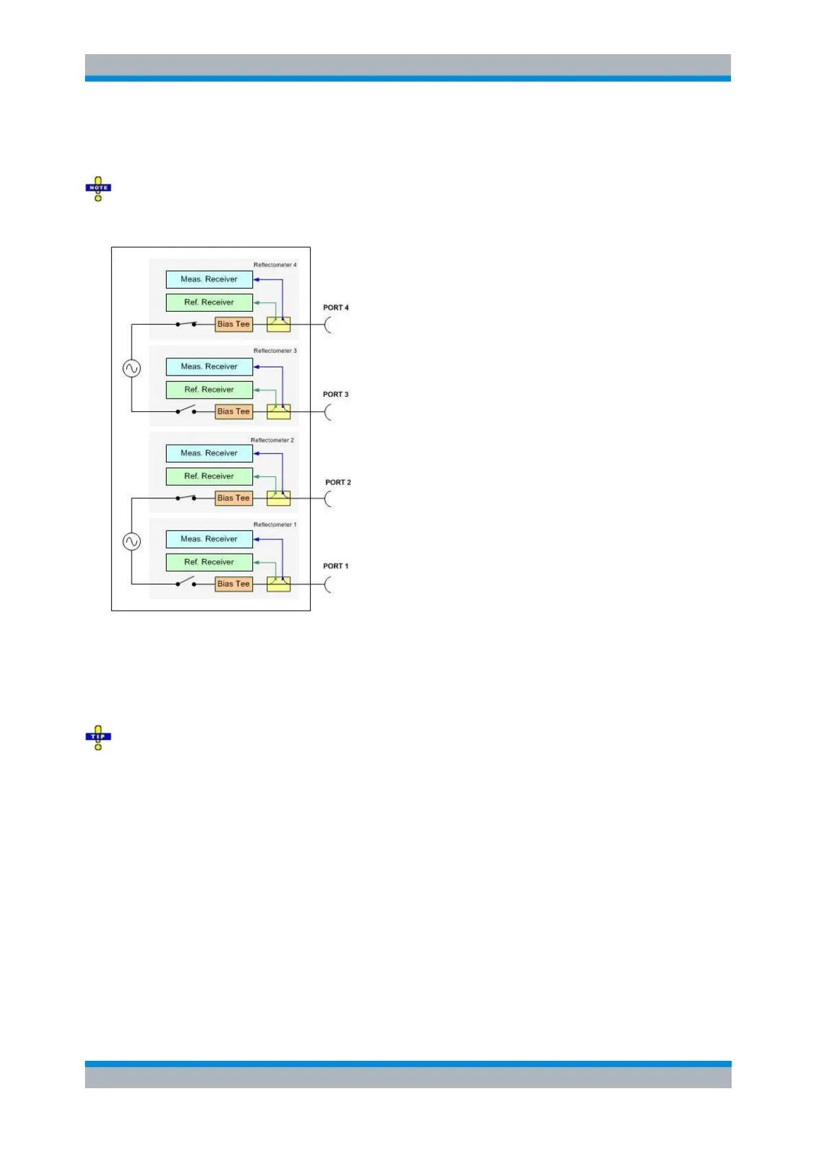
Coupled test ports
For most R&S ZVA analyzers ports 2k-1 and 2k are supplied by a common generator as shown below.
If the RF signal is simultaneously fed to two coupled ports (i.e. if Gen is switched on so that at least one
signal source is permanent), the port frequencies must be the same. For normal measurements (Gen
switched off), this restriction does not apply because there is only one source port per partial
measurement.
The frequency formula for a permanent signal source is also used for the second (coupled) test port.
On R&S ZVA67 and on R&S ZVA24/40 network analyzers with four ports and four generators (order
nos. 1145.1110.28/48), all four ports have independent internal sources. You can configure and combine
the ports without restrictions.
Frequency Result displays the current frequency range (for frequency sweeps) or CW frequency
(for power, time and CW Mode sweeps); see stimulus parameters.
Power opens an input box to define a port-specific source power range (for power sweeps) or
fixed power (for frequency and CW sweeps). The result (not taking into account a possible Slope)
is indicated in the Power Result column. In the default configuration the stimulus parameters
(sweep range, internal source Power) are used.
For frequency converter ports the port-specific power can be defined in a separate dialog; see
Converter Port <n> Power. In this case Port<n> power can only be edited if the power control
method of the related converter port is either set to None or Mechanical Attenuator or to Electronic
Attenuator only.
Power Result displays the current power range (for power sweeps) or fixed internal source power
(for frequency, time and CW Mode sweeps); see stimulus parameters.