R&S
®
ZVA / R&S
®
ZVB / R&S
®
ZVT System Overview
Calibration Overview
Operating Manual 1145.1084.12 – 30 53
calibration types the magnitude and phase response of each calibration standard (i.e. its S-
parameters if no system errors occur) must be known within the entire sweep range. In some
calibration procedures (TRL, TNA, TRM), part of the characteristics of the standards can be auto-
determined due to implicit redundancy (self-calibration).
2. The analyzer compares the measurement data of the standards with their known, ideal response.
The difference is used to calculate the system errors using a particular error model (calibration
type) and derive a set of system error correction data.
3. The system error correction data is used to correct the measurement results of a DUT that is
measured instead of the standards.
Calibration is always channel-specific because it depends on the hardware settings, in particular on the
sweep range. The means that a system error correction data set is stored with the calibrated channel.
The analyzer provides a wide range of sophisticated calibration methods for all types of measurements.
Which calibration method is selected depends on the expected system errors, the accuracy requirements
of the measurement, on the test setup and on the types of calibration standards available.
Due to the analyzer's calibration wizard, calibration is a straightforward, menu-guided process. Moreover,
it is possible to perform the entire calibration process automatically using a Calibration Unit (accessories
R&S ZV-Z5x).
The system error correction data determined in a calibration procedure are stored on the analyzer.
You can read these correction data using the remote control command
[SENSe<Ch>:]CORRection:CDATa. You can also replace the correction data of the analyzer by your
own correction data sets.
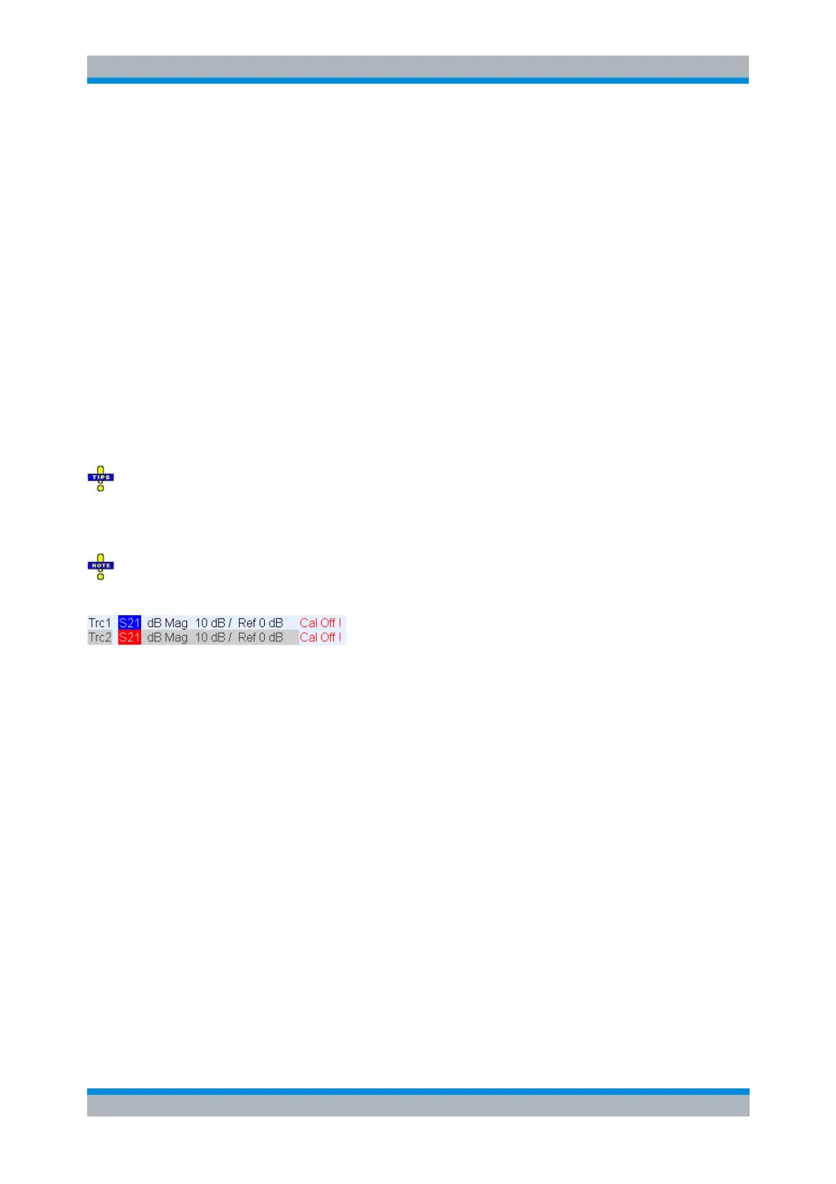
A red label Cal Off ! appears behind the trace list if the system error correction no longer applies to
one or more traces:
This may happen for one of the following reasons:
– The sweep range is outside the calibrated frequency range.
– The measurement result is a wave quantity or ratio which is never system error corrected (see Data
Flow).
– The channel calibration is not sufficient for the measured quantity (e.g. a one-port calibration has been
performed, but the measured quantity is a transmission parameter).
– The system error correction has been switched off deliberately (Correction Off).
The analyzer provides other labels to indicate the status of the current calibration; see Calibration State
Labels.
Calibration Standards and Calibration Kits
A calibration kit is a set of physical calibration standards for a particular connector type. The magnitude
and phase response of the calibration standards (i.e. their S-parameters) must be known or predictable
within a given frequency range.
The standards are grouped into several types (Open, Through, Match,...) corresponding to the different
input quantities for the analyzer's error models. The standard type also determines the equivalent circuit
model used to describe its properties. The circuit model depends on several parameters that are stored in
the cal kit file associated with the calibration kit.
As an alternative to using circuit models, it is possible to describe the standards by means of S-parameter