R&S
®
ZVA / R&S
®
ZVB / R&S
®
ZVT Annexes
Universal Interface (R&S ZVA and R&S ZVB)
Operating Manual 1145.1084.12 – 30 1150
Universal Interface
Universal Interface (R&S ZVA and R&S ZVB)
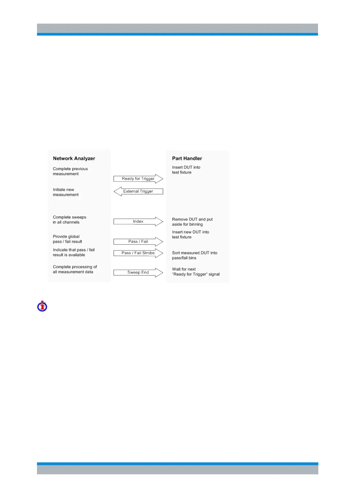
A network analyzer which is equipped with option R&S ZVAB-B14, Universal Interface, can interact with
an external part handler. The digital control signals on the interface connector indicate the possible start
and the end of a measurement, as well as a global limit check result. Typically, the handler will insert the
device to be tested into a test fixture, provide a trigger pulse to initiate the measurement, remove and
replace the device after the measurement is complete and sort it into pass/fail bins. A sample flow
diagram for this process is shown below.
Possible stages of an automated test
Preparation of the network analyzer and the part handler
The network analyzer configuration depends on the measurement to be made. Starting from the preset
state, you will usually have to adjust the following settings:
Enable external trigger: Channel – Sweep – Trigger – External
(Optional:) Select single sweep mode: Channel – Sweep – Single(All Chans)
Define limit lines and enable the limit check: Trace – Lines – Define Limit Line....
The Universal Interface connector must be connected to the part handler using an appropriate cable. If
required, configure the data ports to ensure that the network analyzer and the part handler are compatible.
Control Signals
Most of the signals in the figure below are controlled by the measurement. It is possible though to
configure the Output 1 and Output 2 signals and to route the Index and Ready for Trigger signals using
SCPI commands.
The CONTrol:HANDler:OUTPut<port>... commands set the output signals to a definite state