R&S
®
ZVA / R&S
®
ZVB / R&S
®
ZVT Annexes
Universal Interface (R&S ZVA and R&S ZVB)
Operating Manual 1145.1084.12 – 30 1155
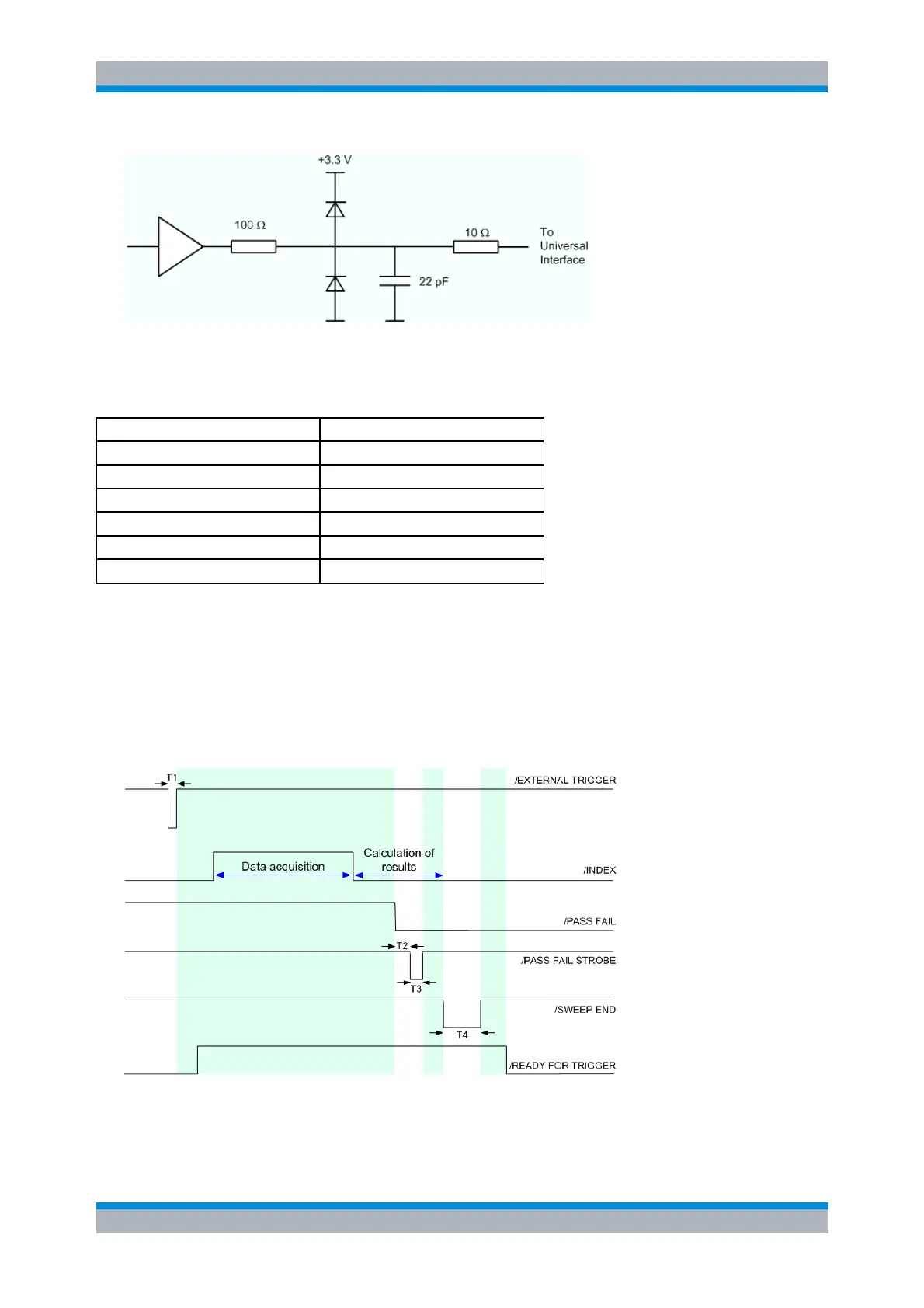
Circuit diagram of the output path
The default configuration of the signals is listed below. Notice that *RST or Preset do not change the
configuration of the Universal Interface. Use CONTrol:HANDler:RESet to restore default values.
Output ports, all bits "High" (decimal 0)
/PORT C STATUS, /PORT D STATUS
CONTrol:HANDler:RESet (resets all configurable signals)
Timing of Control Signals
The timing of the essential measurement control signals is shown in the figure below. The duration of the
shaded time intervals depends on the measurement settings.
Timing of measurement control signals
The figure above contains the following pulse durations and response times.


 To Next Page