Loss
DC
= Loss(f
ref
) = 0 dB. In practice, the frequency-dependent loss often represents the dominant
contribution so that Loss
DC
can be set to zero.
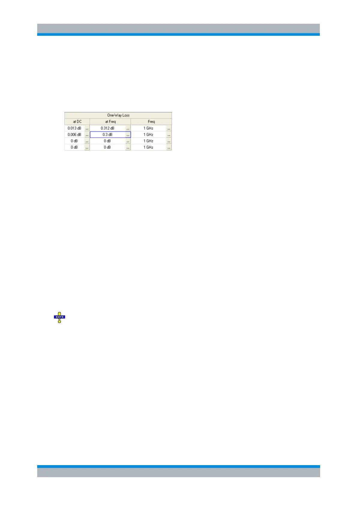
The entries in the One-Way Loss section of the offset dialogs have the following meaning: DC loss
Loss
DC
(at DC), total loss at the reference frequency Loss(f
ref
) (at Freq), reference frequency f
ref
(Freq). Experimentally, the two loss values Loss
DC
and Loss(f
ref
) are determined in two separate
measurements at a very low frequency (f --> 0) and at f = f
ref
.
Offset parameters: Application and effect
Offset parameters can be particularly useful if the reference plane of the calibration cannot be
placed directly at the DUT ports, e.g. because the DUT has non-coaxial ports and can only be
measured in a test fixture. Offset parameters can also help to avoid a new complete system error
correction if a cable with known properties has to be included in the test setup.
A positive length offset moves the reference plane of the port towards the DUT, which is
equivalent to deembedding the DUT by numerically removing a (perfectly matched)
transmission line at that port.
A negative offset moves the reference plane away from the DUT, which is equivalent to
embedding the DUT by numerically adding a (perfectly matched) transmission line at that
port.
The offset parameters are also suited for length and delay measurements; see Auto Length. In
contrast to embedding/deembedding by means of the Channel – Mode – Virtual Transform
functions, the offset parameters cannot compensate for a possible mismatch in the test setup.
Each offset parameter is assigned to a particular port. The delay parameters affect the phase of all
measured quantities related to this port; the loss parameters affect their magnitude. An offset at
port 1 affects the S-parameters S
11
, S
21
, S
12
, S
31
... Some quantities (like the Z-parameters) depend
on the whole of all S-parameters, so they are all more or less affected when one S-parameter
changes due to the addition of an offset length.
To account for the propagation in both directions, the phase shift of a reflection parameter due
to a given length offset is twice the phase shift of a transmission parameter. If, at a frequency of
300 MHz, the electrical length is increased by 250 mm (λ/4), then the phase of S
21
increases by 90
deg, whereas the phase of S
11
increases by 180 deg. Equivalent relations hold for the loss.
If the trace is displayed in Delay format, changing the offset parameters simply shifts the whole
trace in vertical direction. The sign of the phase shift is determined as follows:
A positive offset parameter causes a positive phase shift of the measured parameter and
therefore reduces the calculated group delay.
A negative offset parameter causes a negative phase shift of the measured parameter and
therefore increases the calculated group delay.
Offset parameters for balanced ports
The functions in the Offset menu can be used for balanced port configurations:
If a balanced port configuration is active the logical and physical ports are shown in the
Electrical Length, Mechanical Length and Delay dialogs.