R&S
®
ZVA / R&S
®
ZVB / R&S
®
ZVT GUI Reference
System Menu
Operating Manual 1145.1084.12 – 30 547
In order to set a particular attenuation, e.g. 3 dB, with the mechanical attenuator at port n, proceed as
follows:
1. Turn the converter's adjustment knob counter-clockwise until the mechanical stop is reached.
2. Select wave a<n> as measured quantity (Trace – Measure – Wave Quantities – a<n> Src Port
<n>).
3. Store the a<n> trace to the memory (Trace – Trace Funct – Data -> Mem).
4. Select the mathematical trace mode Trace – Trace Funct – Math = Data / Mem.
5. Slowly turn the knob clockwise until the mathematical trace has been shifted down by 3 dB. Keep
the knob at this position.
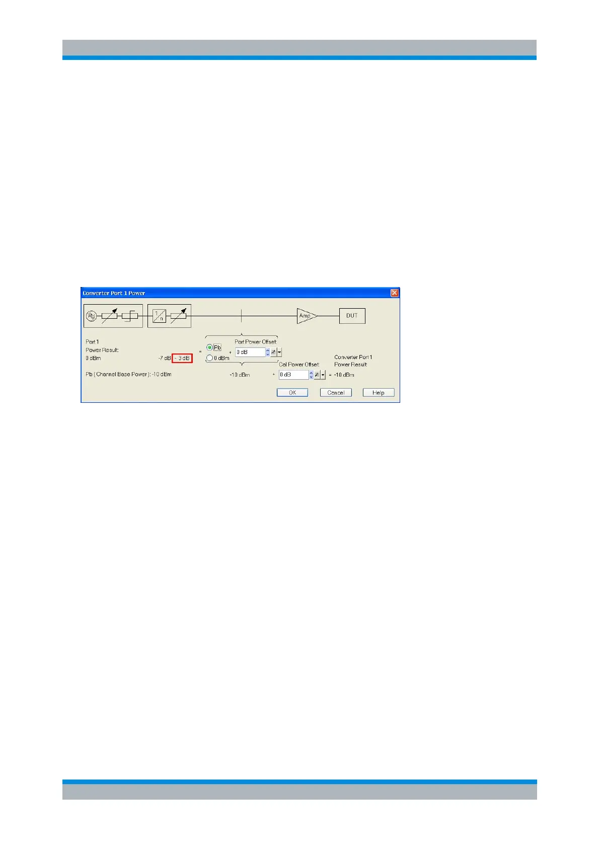
The waveguide attenuation caused by the adjustment screw is also shown in the Converter Port <n>
Power dialog. The analyzer will increase its port power, compensating for the power reduction selected in
the first step. The converter's output power is reduced by 3 dB.
SOURce<Ch>:POWer<Pt>:CONVerter:TRANsfer:DESCription
SOURce<Ch>:POWer<Pt>:CONVerter:TRANsfer:SLOPe
SOURce<Ch>:POWer<Pt>:CONVerter:TRANsfer:OFFSet
SOURce<Ch>:POWer<Pt>:CONVerter:TRANsfer:ATTenuator
SOURce<Ch>:POWer<Pt>:CONVerter:TRANsfer:MECHanical:ATTenaution
SOURce<Ch>:POWer<Pt>:CONVerter:TRANsfer:ELECtronic:LIMit
SOURce<Ch>:POWer<Pt>:CONVerter:TRANsfer:ELECtronic:REDuction
SOURce<Ch>:POWer<Pt>:CONVerter:TRANsfer:ELECtronic:MATTenuation
Connecting the Frequency Converters
Each frequency converter must be connected to the DUT, the network analyzer, and the power supply.
The DUT is screwed on the waveguide flange at the front of the converter. The remaining connectors are
located on the rear panel of the converter (left: R&S ZVA-Zxxx; right: R&S ZCxxx):