R&S
®
ZVA / R&S
®
ZVB / R&S
®
ZVT GUI Reference
System Menu
Operating Manual 1145.1084.12 – 30 548
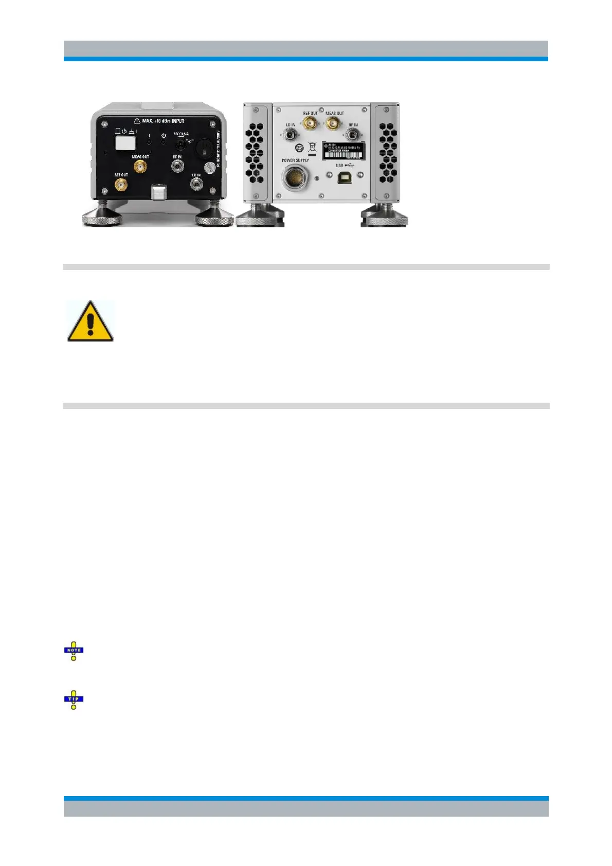
Input powers RF IN and LO IN
The RF input power at the connectors RF IN and LO IN must not exceed the
maximum values quoted in the data sheet. The maximum values are below the
maximum RF source power of the network analyzer. The frequency converter mode
ensures compatible source powers.
Before you connect your converter to the network analyzer, always activate the
frequency converter mode using the Frequency Converter dialog and select the proper
converter type and connecting diagram.
Connection to the network analyzer comprises the following RF input and output signals:
1. RF source signal (input): Connect port 1 or port 2 of the analyzer to RF IN of the converters.
2. LO signal (input): Connect port 3 or port 4 of the analyzer to LO IN of the converters. If a R&S
ZVA24 var. 28, a R&S ZVA40 var. 48 or a R&S ZVA67 is used as NWA, take the LO signal from
NWA port 4 and split it to both converters via a power divider. Alternative: Connect an external
generator signal to LO IN; see Frequency Converter dialog.
3. Reference signal (output): Connect REF OUT of the converters to the REF IN connector of the
analyzer port providing the RF source signal. The reference signal corresponds to the incident
wave (a-wave) applied to the input of the DUT.
4. Measurement signal (output): Connect MEAS OUT of the converters to the MEAS IN connector of
the analyzer port providing the RF source signal. The measured signal corresponds to the b-wave
caused due to reflection or transmission at the DUT.
For converters with electronic attenuators, an additional control connection between the 3-pin output
connector of option R&S ZVA-B8 (EXTATT CTRL) on the front panel of the analyzer and the
corresponding control connector at the rear panel of the converter is required. Observe the port
assignment of the NWA output connector.
The input signals at the frequency converters must be stable over the entire sweep range. Use high-
quality cables for the connection of the RF and LO input signals. Appropriate cables for the REF OUT and
MEAS OUT signals are supplied with the frequency converters.
Due to the port arrangement at the front panel of the analyzer, it is advantageous to use test ports 1
and 2 as RF sources, ports 3 and 4 as LO sources. The frequencies of the RF and LO signal must be
independent, therefore do not combine a pair of ports as RF and LO sources that is supplied by a
common generator (ports 1 and 2, 3 and 4; see Coupled test ports).