R&S
®
ZVA / R&S
®
ZVB / R&S
®
ZVT GUI Reference
System Menu
Operating Manual 1145.1084.12 – 30 549
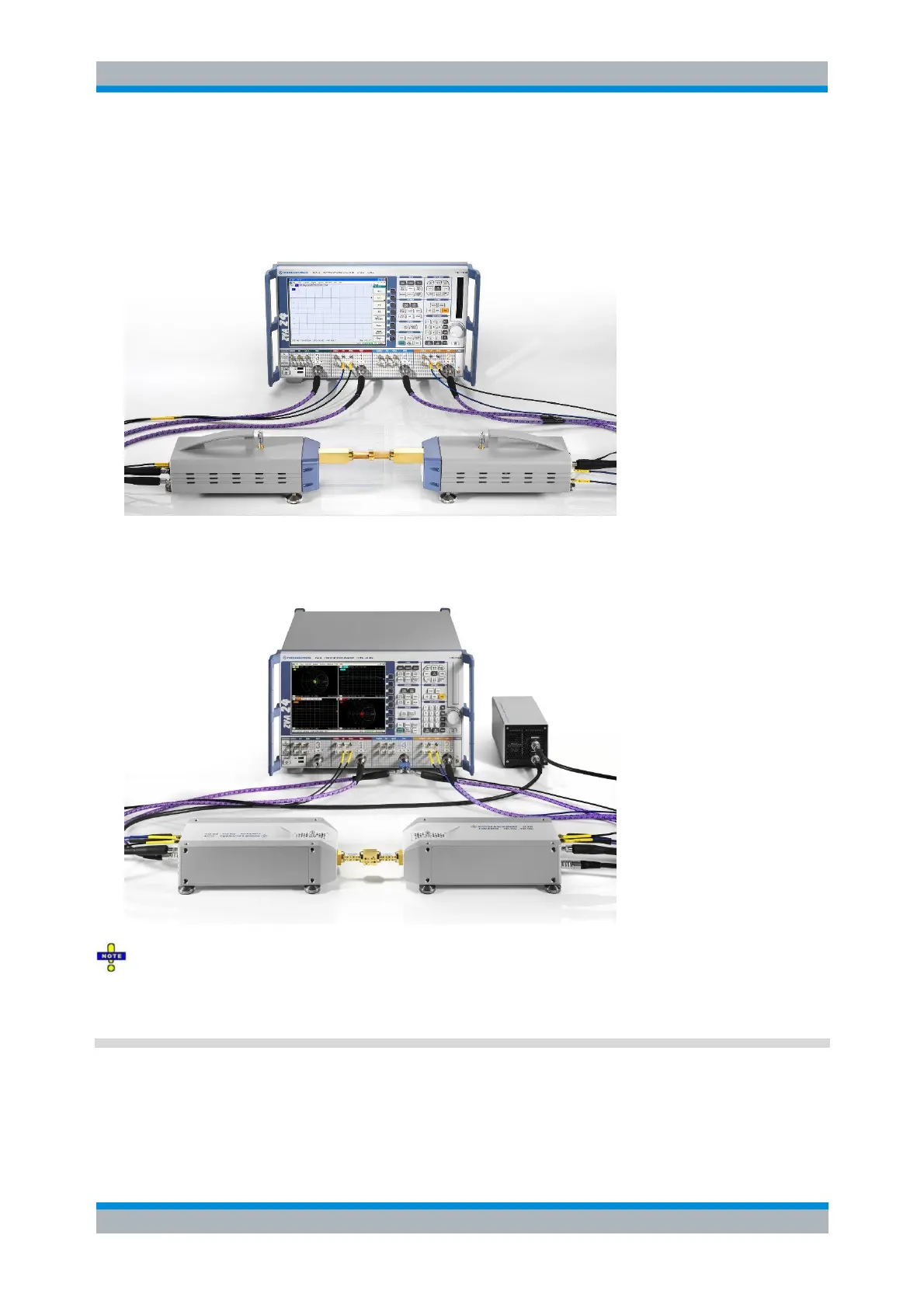
To supply frequency converters of the R&S ZVA-Zxxx series, connect the external DC power supply
provided with the converter to the 9 V DC input. To supply frequency converters of the R&S ZCxxx series,
connect the converter to the power supply R&S ZCPS by means of the DC cable provided with the
converter. A complete test setup for a two-port transmission measurement using converters of the ZVA-
Zxxx series (without electronic attenuators) is shown below.
As mentioned above, when a NWA with four sources is used, Port 4 serves as common drive port. A
complete test setup for a two-port transmission measurement using converters of the ZCxxx series
and an NWA with four sources is shown below.
Frequency converters and true differential mode
To generate a true differential signal with two frequency converters, a modified test setup with three
independent sources is required. See background information in Balanced Ports and Port Groups – True
Diff Mode.
Supply voltage and power
The input voltage and current must not exceed the maximum values according to the
rear panel labeling or the data sheet.