R&S
®
ZVA / R&S
®
ZVB / R&S
®
ZVT GUI Reference
Channel Menu
Operating Manual 1145.1084.12 – 30 444
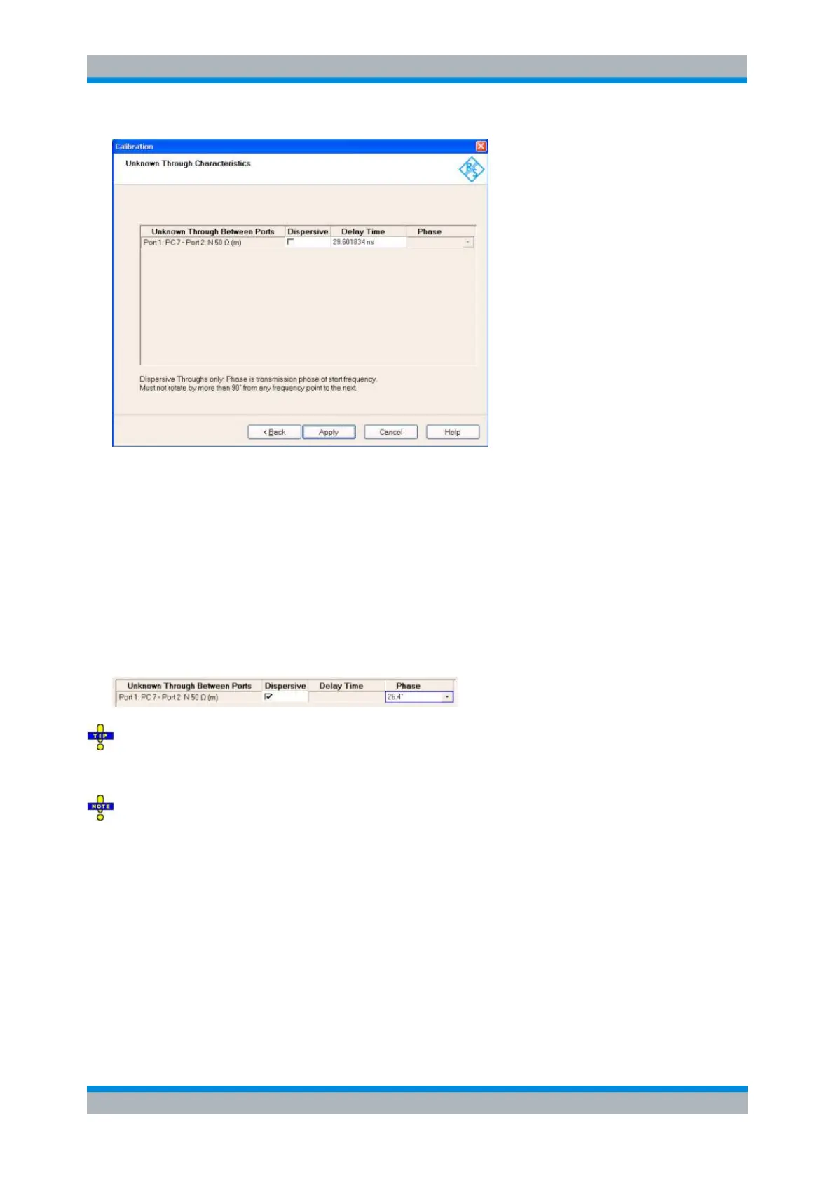
The Unknown Through Characteristics dialog shows the delay time or transmission phase that the
analyzer determined during the calibration sweep.
For a non-dispersive standard (Dispersive check box cleared), the Delay Time can be determined
unambiguously. In this case it is sufficient to press Apply in order to calculate the system error
correction data and close the calibration wizard.
For a dispersive standard (Dispersive check box selected), the delay time is frequency-
dependent, however, the analyzer can determine two solutions for the transmission phase at the
start frequency of the calibration sweep. The two solutions differ by 180 deg; the right solution
must be selected from a drop-down list. The analyzer assumes that the transmission phase
difference between two consecutive sweep points is below 90 deg (make sure that the spacing
between the sweep points is small enough).
If you are not sure which one of the two phases for a dispersive standard is correct, select one, press
Apply and check the measured result. If the transmission phase looks incorrect, use Channel – Calibration
– Repeat Previous Cal... to select the alternative solution.
You can correct the delay time or phase determined by the analyzer manually e.g. by entering a value
derived from the mechanical length of the standard. Doubtful delay times or phases are displayed with a
question mark.
Reference Plane Transformation (NIST Multiline TRL only)
By default the reference plane for a calibration is at the connector plane. Since in addition to the error
correction terms a NIST Multiline TRL calibration produces an accurate propagation constant for each
frequency point, this result can be used to apply a reference plane transformation following the calibration.
In case of a NIST Multiline TRL calibration the Reference Plane Transformation dialog is displayed to
provide the user with a UI to specify the desired transformation.