R&S
®
ZVA / R&S
®
ZVB / R&S
®
ZVT Measurement Examples
Calibration
Operating Manual 1145.1084.12 – 30 76
5. Click Apply to start the calculation of the system error correction data, apply them to the current
channel and close the calibration wizard.
6. Replace the last measured standard with your DUT and perform calibrated measurements without
changing the channel settings used for calibration.
NIST Multiline TRL with 5 Lines using a TEM connector
In the following example you will create a new connector type and calibration kit to perform a Two-Port
NIST Multiline TRL calibration using 5 lines. You will also perform an optional reference plane
transformation and store the calibration results for later use.
In order to create a user-defined calibration kit with 5 Lines, proceed as follows:
1. Click Channel – Calibration – Cal Kits and use the Calibration Kits dialog to add a new TEM
connector for use with the new calibration kit. Click Avail Conn Types… to open the Available
Connector Types dialog. Click Add Type and the […] button in the Offset Model column to enter
the Relative Permittivity ε
r
.
2. Close both dialogs to return to the Calibration Kits dialog, select the calibration kit assigned to the
connector created in step 1 and click Copy Kit to... to create a copy using a new cal kit name.
3. Click View / Modify Kit… to open the View / Modify Calibration Kit dialog and make sure you
select the desired mode: Check Agilent Mode if you wish to use a delay to characterize your
standards or uncheck Agilent Mode to use electrical lengths instead.
4. (Optional) Remove all standards except for Through, Reflect and the 3 Line standards of the
appropriate gender.
5. Update the characteristics of the existing Through, Reflect and the 3 Line standards. Select each
standard in turn and click View / Modify Standard to enter the appropriate values in the View /
Modify Standard dialog.
6. Click Add Standard… to add the remaining 2 Line standards (Line 4 and Line 5) selecting the
appropriate gender and characteristic data. Note that the Add Standard dialog only has a single
Line entry in the Type combo box. When you select the Line entry an additional index field will be
displayed.
In order to perform the manual calibration, proceed as follows:
1. Click Channel – Calibration – Start Cal – Two-Port P1 P2 – NIST Multiline TRL… to launch the
calibration wizard.
2. Select the connector created above and click Next >.
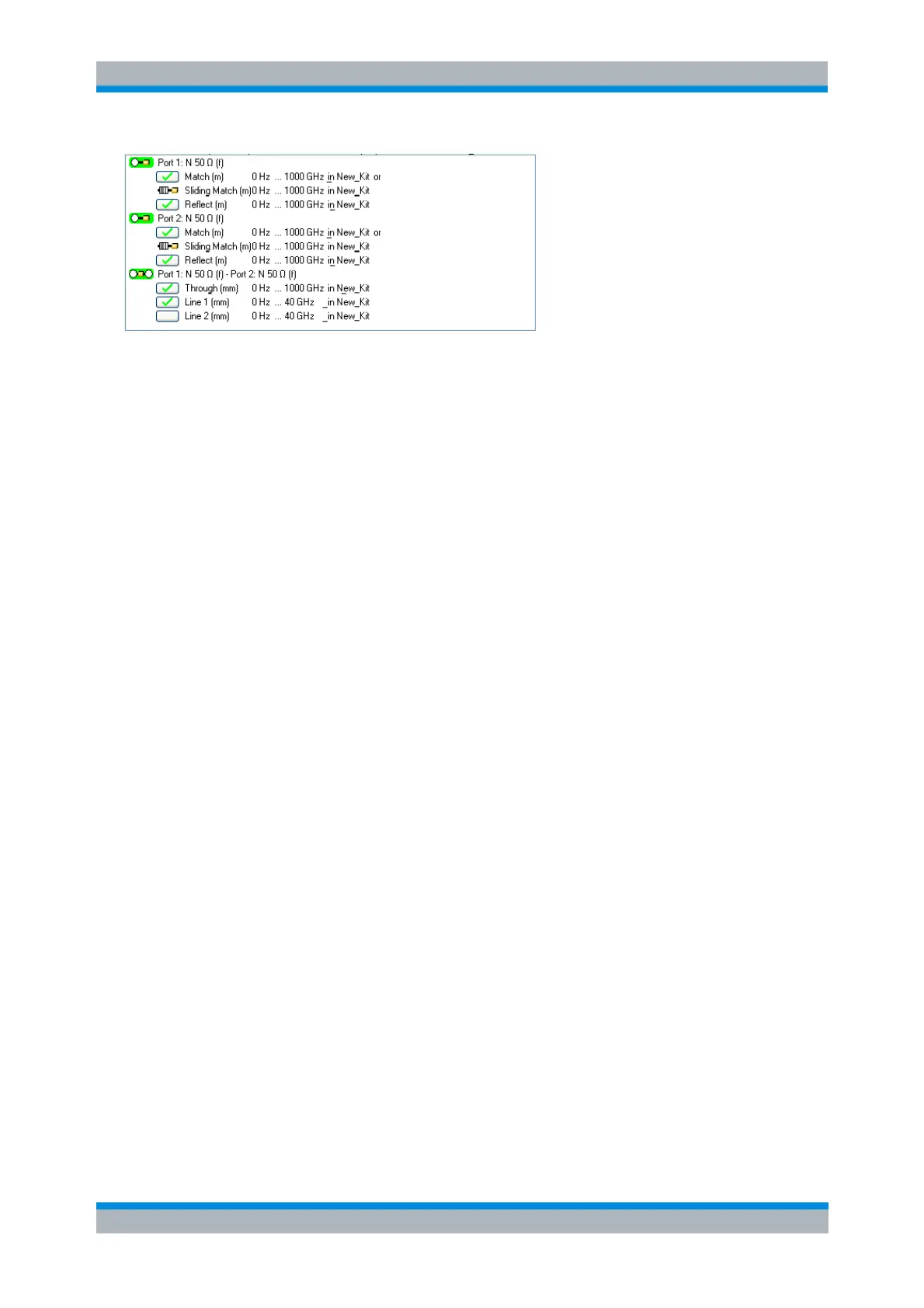
3. Connect the standards in turn and record the corresponding calibration sweeps.
Note that the Next > button is enabled as soon as the Reflect, Through, and one of the Line
measurements have been performed. While not strictly mandatory it is highly recommended to
perform the remaining line measurements to significantly increase the accuracy of the calibration.
Once all standards have been measured click Next > to move to the Reference Plane
Transformation dialog.