6
6-12
INTERNAL MEMORY
32180 Group User’s Manual (Rev.1.0)
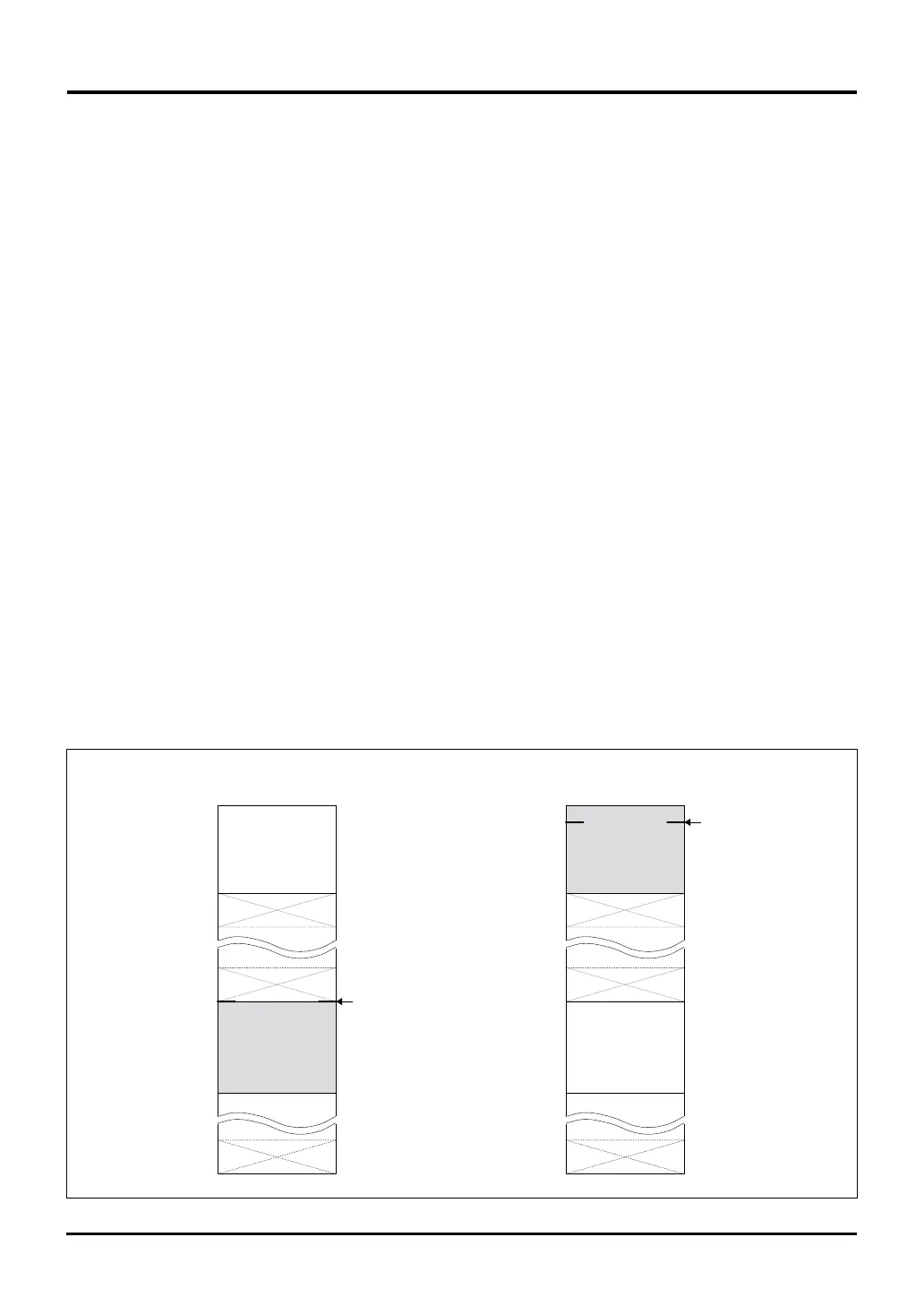
Figure 6.5.1 EI Vector Entry during Flash E/W Enable Mode
EI vector entry
(H'0000 0080)
Internal ROM area
Internal RAM
H'0000 0000
H'00FF FFFF
H'0080 4000
Internal ROM area
Internal RAM
H'0080 3FFF
Flash E/W enable mode
(FENTRY = 1)
Normal mode
(FENTRY = 0)
H'0000 0000
H'0080 3FFF
EI vector entry
(H'0080 4000)
H'0080 4000
H'00FF FFFF
6.5 Programming the Internal Flash Memory
6.5 Programming the Internal Flash Memory
6.5.1 Outline of Internal Flash Memory Programming
To program or erase the internal flash memory, there are following two methods to choose depending on the
situation:
(1) When the flash write/erase program does not exist in the internal flash memory
(2) When the flash write/erase program already exists in the internal flash memory
For (1), set the FP pin = "high", MOD0 = "high" and MOD1 = "low" to enter boot mode. In this case, the CPU
starts running the boot program immediately after reset.
The boot program transfers the flash write/erase program into the internal RAM. After the transfer, jump to a
location in the RAM and use the RAM-resident program to set the Flash Control Register 1 (FCNT1) FENTRY bit
to "1" to make the internal flash memory ready for programming/erase operation (i.e., placed in boot mode +
flash E/W enable mode).
When the above is done, use the flash write/erase program that has been transferred into the internal RAM to
program or erase the internal flash memory.
For (2), set the FP pin = "high", MOD0 = "low" and MOD1 = "low" to enter single-chip mode. Transfer the flash
write/erase program from the internal flash memory in which it has been prepared into the internal RAM. After
the transfer, jump to the RAM and use the program transferred into the RAM to set the Flash Control Register 1
(FCNT1) FENTRY bit to "1" to make the internal flash memory ready for programming/erase operation (i.e.,
placed in single-chip mode + flash E/W enable mode).
When the above is done, use the flash write/erase program that has been transferred into the internal RAM to
program or erase the internal flash memory. Or flash E/W enable mode can be entered from external extension
mode by setting the FP pin = "high", MOD0 = "low" and MOD1 = "high".
During flash E/W enable mode (FP pin = 1, FENTRY = 1), the EIT vector entry for External Interrupt (EI) is
relocated to the start address (H’0080 4000) of the internal RAM. During normal mode, it is located in the flash
area (H’0000 0080).

 Loading...


