10
10-134
MULTIJUNCTION TIMERS
10.6 TML (Input-Related 32-Bit Timer)
32180 Group User’s Manual (Rev.1.0)
10.6.4 TML Control Registers
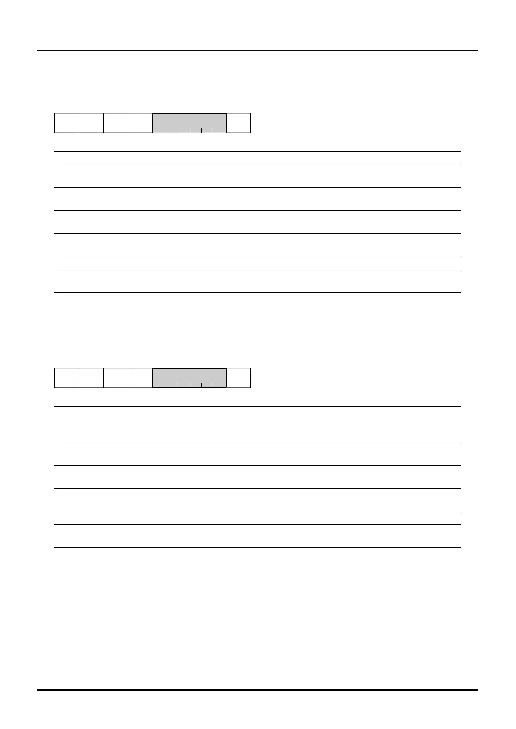
TML0 Control Register (TML0CR) <Address: H’0080 03EB>
9 1011121314b15b8
TML0SS0 TML0SS1 TML0SS2 TML0SS3 TML0CKS
0000 0
<After reset: H’00>
b Bit Name Function R W
8 TML0SS0 0: External input TIN23 R W
TML0 measure 0 source select bit 1: Input event bus 0
9 TML0SS1 0: External input TIN22 R W
TML0 measure 1 source select bit 1: Input event bus 1
10 TML0SS2 0: External input TIN21 R W
TML0 measure 2 source select bit 1: Input event bus 2
11 TML0SS3 0: External input TIN20 R W
TML0 measure 3 source select bit 1: Input event bus 3
12–14 No function assigned. Fix to "0". 00
15 TML0CKS (Note 1) 0: BCLK/2 R W
TML0 clock source select bit 1: Clock bus 1
Note 1: The counter can only be written normally when BCLK/2 is used as the clock source for the counter. If the selected clock
source is not BCLK/2, do not write to the counter because it cannot be written normally.
TML1 Control Register (TML1CR) <Address: H’0080 0FEB>
9 1011121314b15b8
TML1SS0 TML1SS1 TML1SS2 TML1SS3 TML1CKS
0000 0
<After reset: H’00>
b Bit Name Function R W
8 TML1SS0 0: External input TIN33 R W
TML1 measure 0 source select bit 1: Input event bus 0
9 TML1SS1 0: External input TIN32 R W
TML1 measure 1 source select bit 1: Input event bus 1
10 TML1SS2 0: External input TIN31 R W
TML1 measure 2 source select bit 1: Input event bus 2
11 TML1SS3 0: External input TIN30 R W
TML1 measure 3 source select bit 1: Input event bus 3
12–14 No function assigned. Fix to "0". 00
15 TML1CKS (Note 1) 0: BCLK/2 R W
TML1 clock source select bit 1: Clock bus 1
Note 1: The counter can only be written normally when BCLK/2 is used as the clock source for the counter. If the selected clock
source is not BCLK/2, do not write to the counter because it cannot be written normally.
The TML control register is used to select TML input event and count clock.

 Loading...


