15
15-18
EXTERNAL BUS INTERFACE
32180 Group User’s Manual (Rev.1.0)
15.5 Typical Connection of External Extension Memory
15.5 Typical Connection of External Extension Memory
(1) When the Bus Mode Control Register = "0"
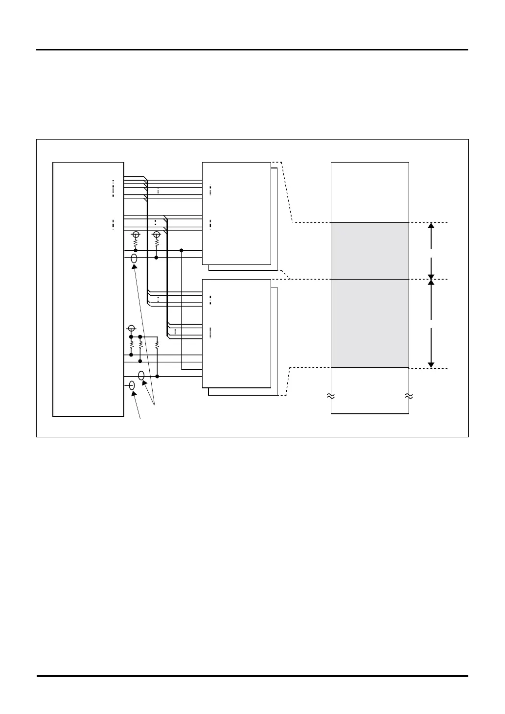
A typical memory connection when using external extension memory is shown in Figure 15.5.1. (External
extension memory can only be used in external extension mode and processor mode.)
Figure 15.5.1 Typical Connection of External Extension Memory (when BUSMOD bit = "0")
Note: • The address and data are connected in such a way that pin 0 is the MSB and pin 15 is the LSB.
When connecting external extension memory, connections of the MSB and LSB sides must be
reversed.
Memory mapping
Internal flash memory
(1024KB)
External memory area
(1MB)
Number of bus wait states can be set to 0-7.
Normally used as port. WAIT is used only when seven or more wait states are needed.
H'0000 0000
H'0040 0000
H'0020 0000
H'000F FFFF
H'0010 0000
External memory area
(2MB)
1M-CS0 area
2M-CS1 area
SRAM
Flash memory
A18
A0
D15
D0
RD#
CS#
max1MB
A18
A0
D15
D0
RD#(D0-D15)
CS#
WR#(D0-D7)
WR#(D8-D15)
max1MB
*
2
(total2MB)
M32180F8
A11
A30
D0
D15
RD#
CS0#
CS1#
BLW#
BHW#
WAIT#
CS2#
CS3#

 Loading...


