14
14-7
REAL TIME DEBUGGER (RTD)
14.3 Functional Description of the RTD
32180 Group User’s Manual (Rev.1.0)
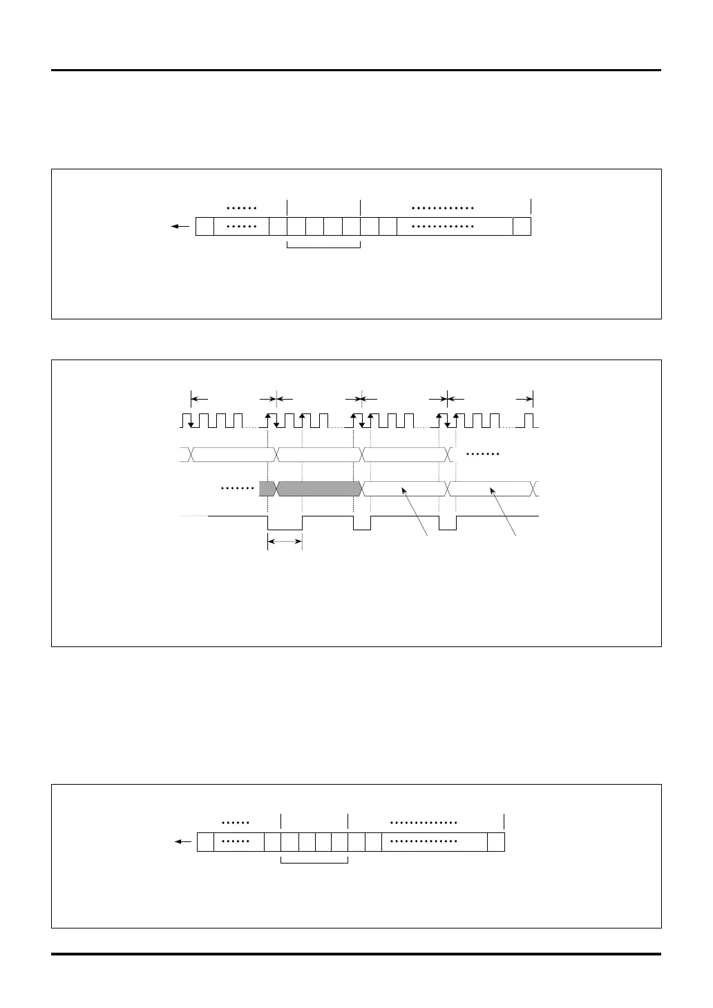
14.3.4 Operation of VER (Continuous Monitor)
When the VER (continuous monitor) command is issued, the RTD outputs the data from the address that has
been accessed by an instruction (either read or write) immediately before receiving the VER command.
Figure 14.3.6 VER (Continuous Monitor) Command Data Format
32 clock
periods
RDR(A1) VER
2 clock periods
RTDCLK
RTDRXD
RTDTXD
RTDACK
D (A1)
Read value
D (A1)
Latest read value
(Note 1)
VER
Note 1: WRR command can also be used.
Notes: • (An) = Specified address
• D(An) = Data at specified address (An)
32 clock
periods
32 clock
periods
32 clock
periods
Figure 14.3.7 Operation of the VER (Continuous Monitor) Command
14.3.5 Operation of VEI (Interrupt Request)
When the VEI (interrupt request) command is issued, the RTD generates an interrupt request. Furthermore, the RTD
outputs the data from the address that has been accessed by an instruction (either read or write) immediately before
receiving the VEI command.
31
X00
00
19 18 17 16
00
15 14
0
X
20
Command (VER)
Notes: • X = Don't care.
(However, if issued immediately after the RCV command, bits 20-31 must all be set to 1.)
RTDRXD
X
(MSB side)
(LSB side)
Figure 14.3.8 VEI (Interrupt Request) Command Data Format
31
X01
10
19 18 17 16
00
15
14 0
X
20
VEI (interrupt request generation) command
RTDRXD
X
Note: • X = Don't care.
(However, if issued immediately after the VEI command, bits 20-31 must all be set to 1.)
(MSB side)
(LSB side)

 Loading...


