10-109
10
10.4 TIO (Input/Output-Related 16-Bit Timer)
MULTIJUNCTION TIMERS
32180 Group User’s Manual (Rev.1.0)
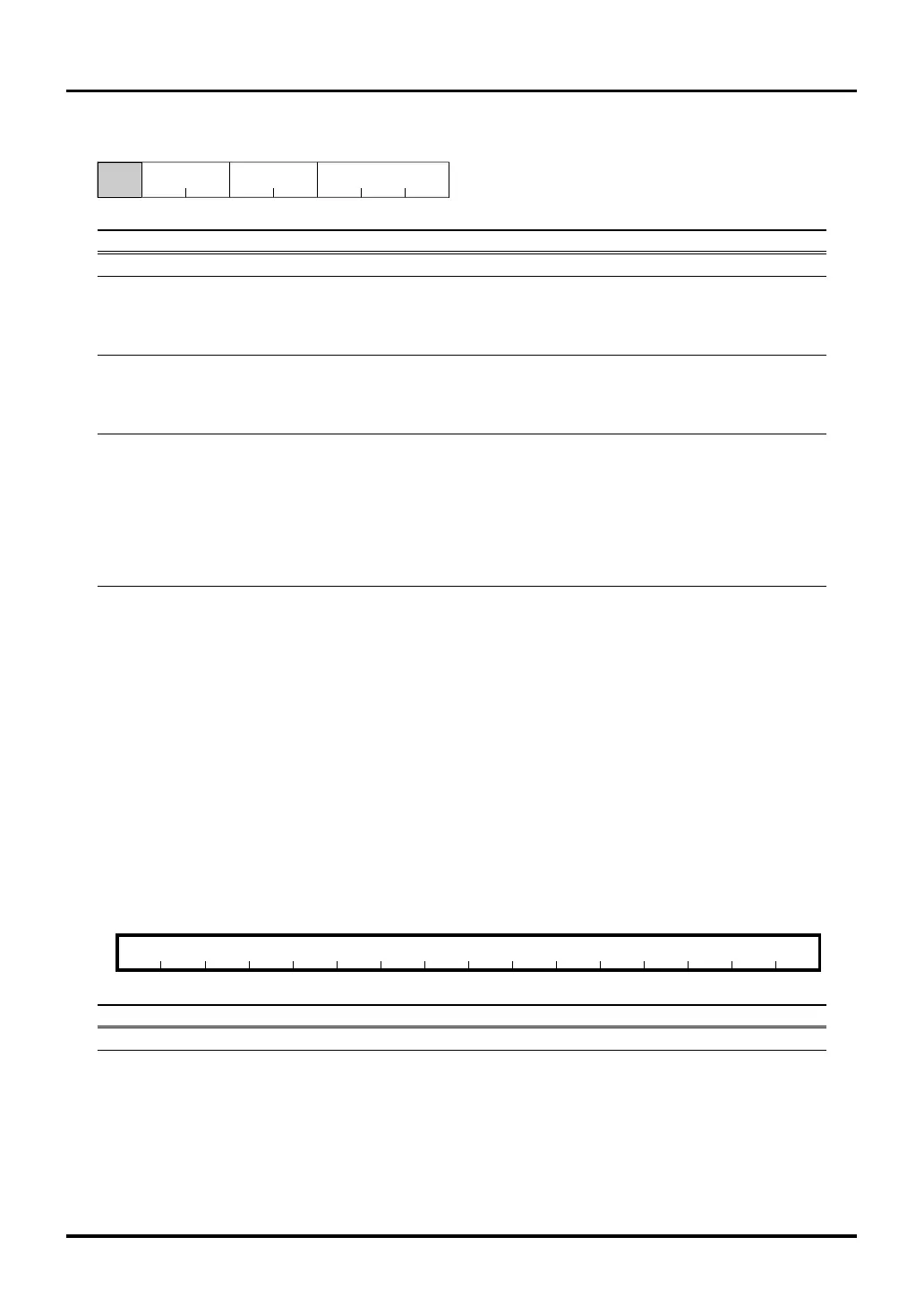
10.4.5 TIO Counters (TIO0CT–TIO9CT)
TIO0 Counter (TIO0CT) <Address: H’0080 0300>
TIO1 Counter (TIO1CT) <Address: H’0080 0310>
TIO2 Counter (TIO2CT) <Address: H’0080 0320>
TIO3 Counter (TIO3CT) <Address: H’0080 0330>
TIO4 Counter (TIO4CT) <Address: H’0080 0340>
TIO5 Counter (TIO5CT) <Address: H’0080 0350>
TIO6 Counter (TIO6CT) <Address: H’0080 0360>
TIO7 Counter (TIO7CT) <Address: H’0080 0370>
TIO8 Counter (TIO8CT) <Address: H’0080 0380>
TIO9 Counter (TIO9CT) <Address: H’0080 0390>
b01234567891011121314b15
TIO0CT–TIO9CT
????????????????
<After reset: Undefined>
b Bit Name Function R W
0–15 TIO0CT–TIO9CT 16-bit reload counter value R(Note 1)
Note 1: Protected against write during PWM output mode.
Note: • This register must always be accessed in halfwords.
The TIO counters are a 16-bit down-counter. After the timer is enabled (by writing to the enable bit in software or
by external input), the counter starts counting synchronously with the count clock.
These counters are protected against write during PWM output mode.
TIO9 Control Register (TIO9CR) <Address: H’0080 038B>
9 1011121314b15b8
TIO9MTIO9CKS TIO9ENS
0000000
<After reset: H’00>
b Bit Name Function R W
8 No function assigned. Fix to "0". 00
9, 10 TIO9CKS 00: Clock bus 0 R W
TIO9 clock source select bit 01: Clock bus 1
10: Clock bus 2
11: Clock bus 3
11, 12 TIO9ENS 00: No selection R W
TIO9 enable/measure input source select bit 01: External input TIN11
10: Input event bus 1
11: Input event bus 3
13–15 TIO9M 000: Single-shot output mode R W
TIO9 operation mode select bit 001: Delayed single-shot output mode
010: Continuous output mode
011: PWM output mode
100: Measure clear input mode
101: Measure free-run input mode
110: Noise processing input mode
111: – ditto –
Note: • Operation mode can only be set or changed while the counter is inactive.

 Loading...


