20
20-3
POWER SUPPLY CIRCUIT
32180 Group User's Manual (Rev.1.0)
20.2 Power-On Sequence
20.2 Power-On Sequence
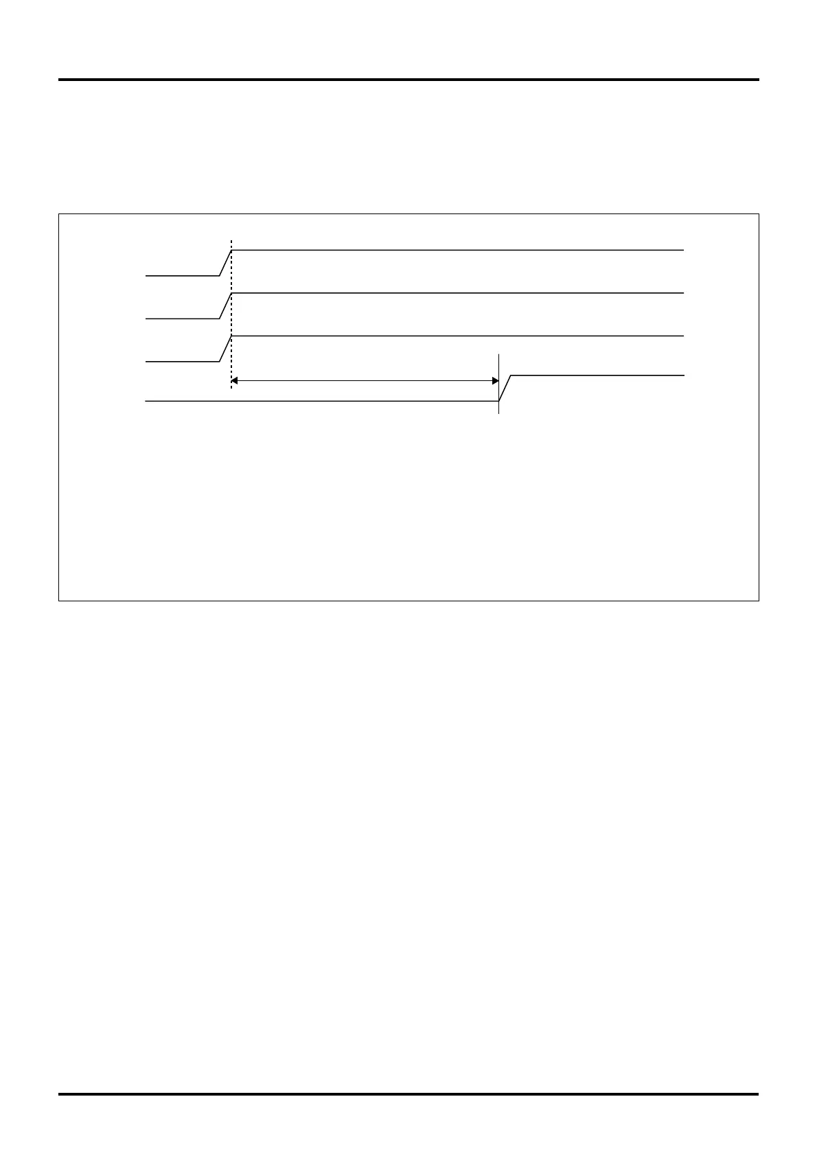
20.2.1 Power-On Sequence when Not Using RAM Backup
The diagram below shows a turn-on sequence of the power supply (5.0 V or 3.3 V) when not using RAM backup.
0V
0V
0V
0V
VCCE,VDDE
VCC-BUS,
OSC-VCC
AVCC
VREF
RESET#
Note 1: After turning on all power supplies and holding the RESET# pin low for an oscillation stabilization time,
release the RESET# pin back high (to deassert the reset input).
Notes: • Power-on limitations
VCCE = OCS-VCC
VDDE ≥ VCCE, OSC-VCC
• However, if the above power-on limitations cannot be met, sufficient evaluation must be made during system design
in order to ensure that no power will be applied to the microcomputer with a potential difference of 1 V or more.
For potential differences 0 V to 0.6 V, there is almost no in-flow current. The amount of in-flow current begins to increase
when the potential difference exceeds 0.6 V.
(Note 1)
Figure 20.2.1 Power-On Sequence when Not Using RAM Backup

 Loading...


