13-15
13
32180 Group User’s Manual (Rev.1.0)
13.2 CAN Module Related Registers
CAN MODULE
13.2.1 CAN Control Registers
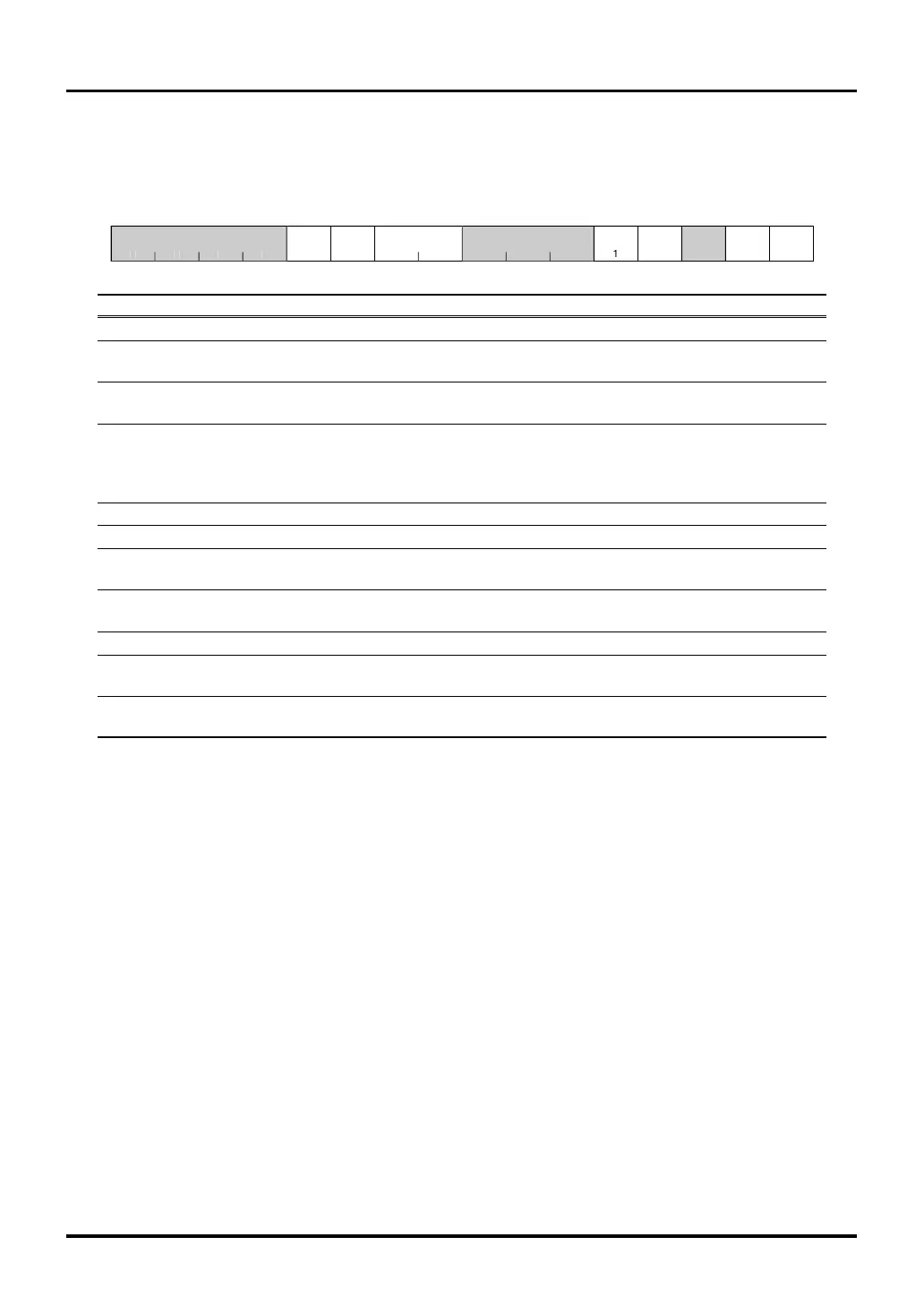
CAN0 Control Register (CAN0CNT) <Address: H’0080 1000>
CAN1 Control Register (CAN1CNT) <Address: H’0080 1400>
b0 1 2 3 4 5 6 7 8 9 10 11 12 13 14 b15
FRS
TS
TSRRB
BCM LBM RST
00
0
01
<After reset: H’0011>
b Bit Name Function R W
0–3 No function assigned. Fix to "0". 00
4 RBO 0: Enable normal operation R(Note 1)
Return bus off bit 1: Request clearing of error counter
5 TSR 0: Enable count operation R(Note 1)
Timestamp counter reset bit 1: Initialize count (to H’0000)
6–7 TSP 00: Select CAN bus bit clock R W
Timestamp prescaler bit 01: Select CAN bus bit clock divided by 2
10: Select CAN bus bit clock divided by 3
11: Select CAN bus bit clock divided by 4
8–9 No function assigned. Fix to "0". 00
10 No function assigned. Fix to "0". 00
11 FRST 0: Negate reset R W
Forcible reset bit 1: Forcibly reset
12 BCM 0: Disable BasicCAN mode R W
BasicCAN mode bit 1: BasicCAN mode
13 No function assigned. Fix to "0". 00
14 LBM 0: Disable loopback function R W
Loopback mode bit 1: Enable loopback function
15 RST 0: Negate reset R W
CAN reset bit 1: Request reset
Note 1: Only writing "1" is effective. Automatically cleared to "0" in hardware.

 Loading...


