11
11-36
A-D Converters
32180 Group User's Manual (Rev.1.0)
11.3 Functional Description of A-D Converters
11.3.4 Calculating the A-D Conversion Time
The A-D conversion time is expressed by the sum of dummy cycle time and actual execution cycle time. The
following shows each time factor necessary to calculate the conversion time.
1. Start dummy time
A time from when the CPU executed the A-D conversion start instruction to when the A-D Converter
starts A-D conversion
2. A-D conversion execution cycle time
If sample-and-hold is enabled, the sampling time is included in this execution cycle time.
3. Comparate execution cycle time
4. End dummy time
A time from when the A-D Converter has finished A-D conversion to when the CPU can stably read out
the conversion result from the A-D data register.
5. Scan to scan dummy time
A time during single-shot or continuous scan mode from when the A-D Converter has finished A-D
conversion on a channel to when it starts A-D conversion on the next channel.
The equation to calculate the A-D conversion time is as follows:
A-D conversion time = Start dummy time + Execution cycle time
(+ Scan to scan dummy time + Execution cycle time
+ Scan to scan dummy time + Execution cycle time
+ Scan to scan dummy time .... + Execution cycle time)
+ End dummy time
Note: • Enclosed in ( ) are the conversion time required for the second and subsequent channels
to be converted in scan mode.
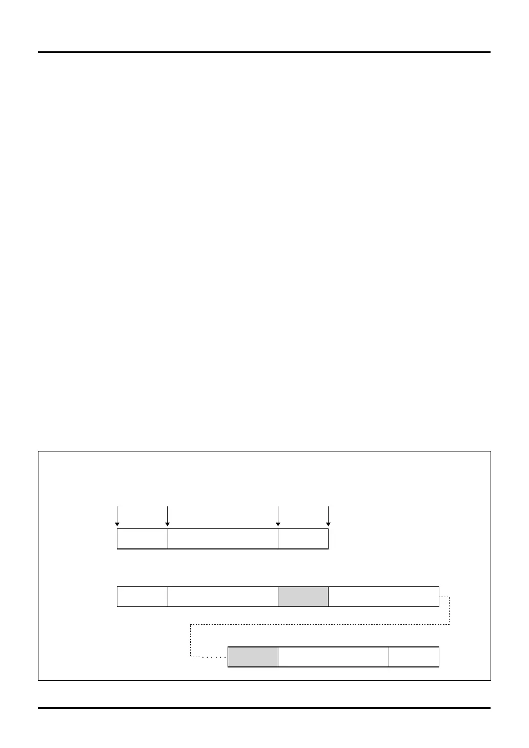
(1) Calculating the conversion time during A-D conversion mode
The following schematically shows the method for calculating the conversion time during A-D conversion mode.
Start dummy Execution cycle
A-D conversion
start trigger
Convert operation
starts
Transferred to the
A-D data register
<Scan mode>
End dummy
Start dummy Execution cycle Execution cycle
<Single mode>
Completed
Execution cycle
End dummy
Scan to
scan dummy
Scan to
scan dummy
(Channel 0) (Channel 1)
(Last channel)
Figure 11.3.3 Conceptual Diagram of A-D Conversion Time

 Loading...


