11
11-37
A-D Converters
32180 Group User's Manual (Rev.1.0)
11.3 Functional Description of A-D Converters
Table 11.3.1 Conversion Clock Periods in A-D Conversion Mode Unit: BCLK
Conversion speed Start dummy (Note 1) Execution cycle End dummy Scan to scan dummy (Note 2)
Slow mode Normal speed 4 294 1 4
Double speed 4 168 1 4
Fast mode Normal speed 4 126 1 4
Double speed 4 84 1 4
Note 1: The same applies to both software and hardware triggers.
Note 2: Only during scan operation, execution time per channel is added.
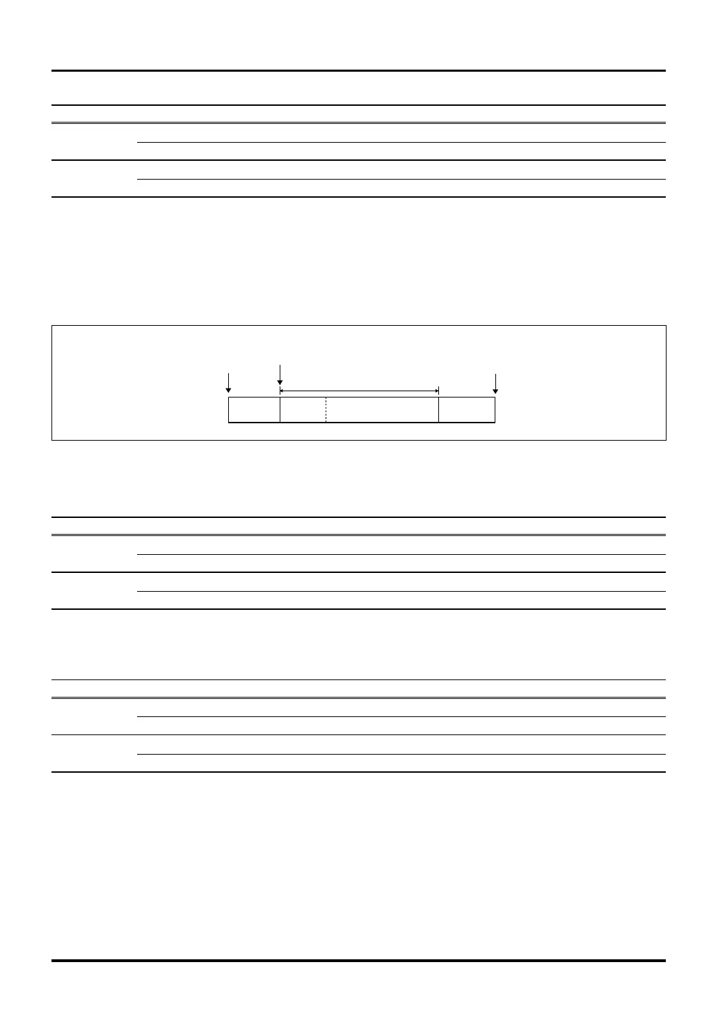
(2) Calculating the conversion time when sample-and-hold is enabled
The following schematically shows the method for calculating the conversion time when the sample-and-hold
function is enabled.
Start dummy
Execution cycle
A-D conversion
start trigger
Convert operation
starts
End dummy
Completed
Sampling
time
Figure 11.3.4 Conceptual Diagram of A-D Conversion Time when Sample-and-Hold is Enabled
Table 11.3.2 Conversion Clock Periods during Normal Sample-and-Hold Mode Unit: BCLK
Conversion speed Start dummy (Note 1) Execution cycle End dummy Scan to scan dummy (Note 2)
Slow mode Normal speed 4 294 1 4
Double speed 4 168 1 4
Fast mode Normal speed 4 126 1 4
Double speed 4 84 1 4
Note 1: The same applies to both software and hardware triggers.
Note 2: Only during scan operation, execution time per channel is added.
Table 11.3.3 Conversion Clock Periods during Fast Sample-and-Hold Mode Unit: BCLK
Conversion speed Start dummy (Note 1) Execution cycle End dummy Scan to scan dummy (Note 2)
Slow mode Normal speed 4 186 1 4
Double speed 4 96 1 4
Fast mode Normal speed 4 90 1 4
Double speed 4 48 1 4
Note 1: The same applies to both software and hardware triggers.
Note 2: Only during scan operation, execution time per channel is added.

 Loading...


