19
19-12
JTAG
32180 Group User's Manual (Rev.1.0)
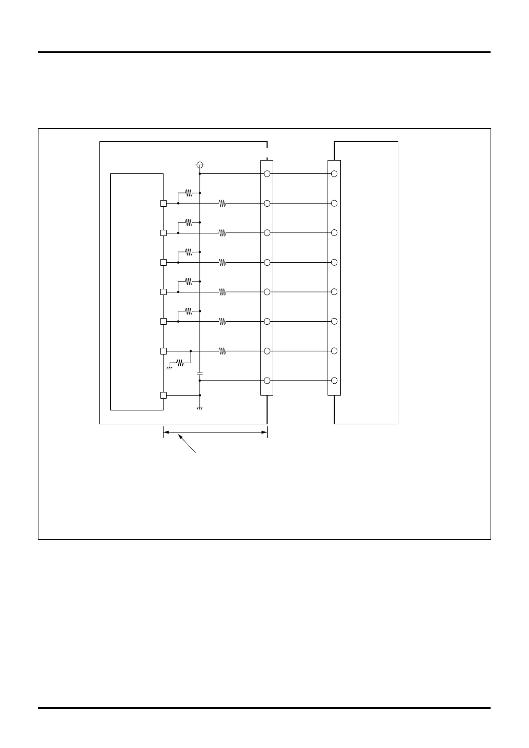
19.6 Notes on Board Design when Connecting JTAG
19.6 Notes on Board Design when Connecting JTAG
To materialize fast and highly reliable communication with JTAG tools, make sure wiring lengths of JTAG pins are
matched during board design.
M32R/ECU
JTDI
JTMS
JTCK
JTRST
User board
JTAG tool
Make sure wiring lengths are the same, and avoid bending wires as much as possible.
Be careful not to use through-holes within the wiring.
JTDO
33Ω
33Ω
VCCE(5V)
33Ω
33Ω
2KΩ
10KΩ
10KΩ
0.1µF
SDI connector (JTAG connector)
Power
TDI
TMS
TCK
TRST
TDO
GND
Note 1: The RESET# related circuit and resistance-capacitance values must be determined depending on
the user board's system design conditions and the microcomputer's operating conditions.
Note 2: N-channel open-drain output is recommended for the RESET output of JTAG tools. For details, see JTAG tool specifications.
Notes: • Only if the JTRST pin is firmly tied to ground, the JTDO, JTDI, JTMS and JTCLK pins can be processed by either pullup or pulldown.
• Each of these pins must always be processed even when not using JTAG tools.
The same pullup/pulldown resistance values as when using JTAG tools may be used.
RESET#
(Note 1)
RESET
(Note 2)
33Ω
10KΩ
VSS
33Ω
10KΩ
10KΩ
Figure 19.6.1 Notes on Board Design when Connecting JTAG Tools (for 240QFP)

 Loading...


