10
10-128
MULTIJUNCTION TIMERS
10.5 TMS (Input-Related 16-Bit Timer)
32180 Group User’s Manual (Rev.1.0)
10.5.3 TMS Related Register Map
Shown below is a TMS related register map.
TMS Related Register Map
Address +0 address +1 address See pages
b0 b7 b8 b15
H'0080 03C0 TMS0 Counter 10-130
(TMS0CT)
H'0080 03C2 TMS0 Measure 3 Register 10-130
(TMS0MR3)
H'0080 03C4 TMS0 Measure 2 Register 10-130
(TMS0MR2)
H'0080 03C6 TMS0 Measure 1 Register 10-130
(TMS0MR1)
H'0080 03C8 TMS0 Measure 0 Register 10-130
(TMS0MR0)
H'0080 03CA TMS0 Control Register TMS1 Control Register 10-129
(TMS0CR) (TMS1CR)
(Use inhibited area)
H'0080 03D0 TMS1 Counter 10-130
(TMS1CT)
H'0080 03D2 TMS1 Measure 3 Register 10-130
(TMS1MR3)
H'0080 03D4 TMS1 Measure 2 Register 10-130
(TMS1MR2)
H'0080 03D6 TMS1 Measure 1 Register 10-130
(TMS1MR1)
H'0080 03D8 TMS1 Measure 0 Register 10-130
(TMS1MR0)
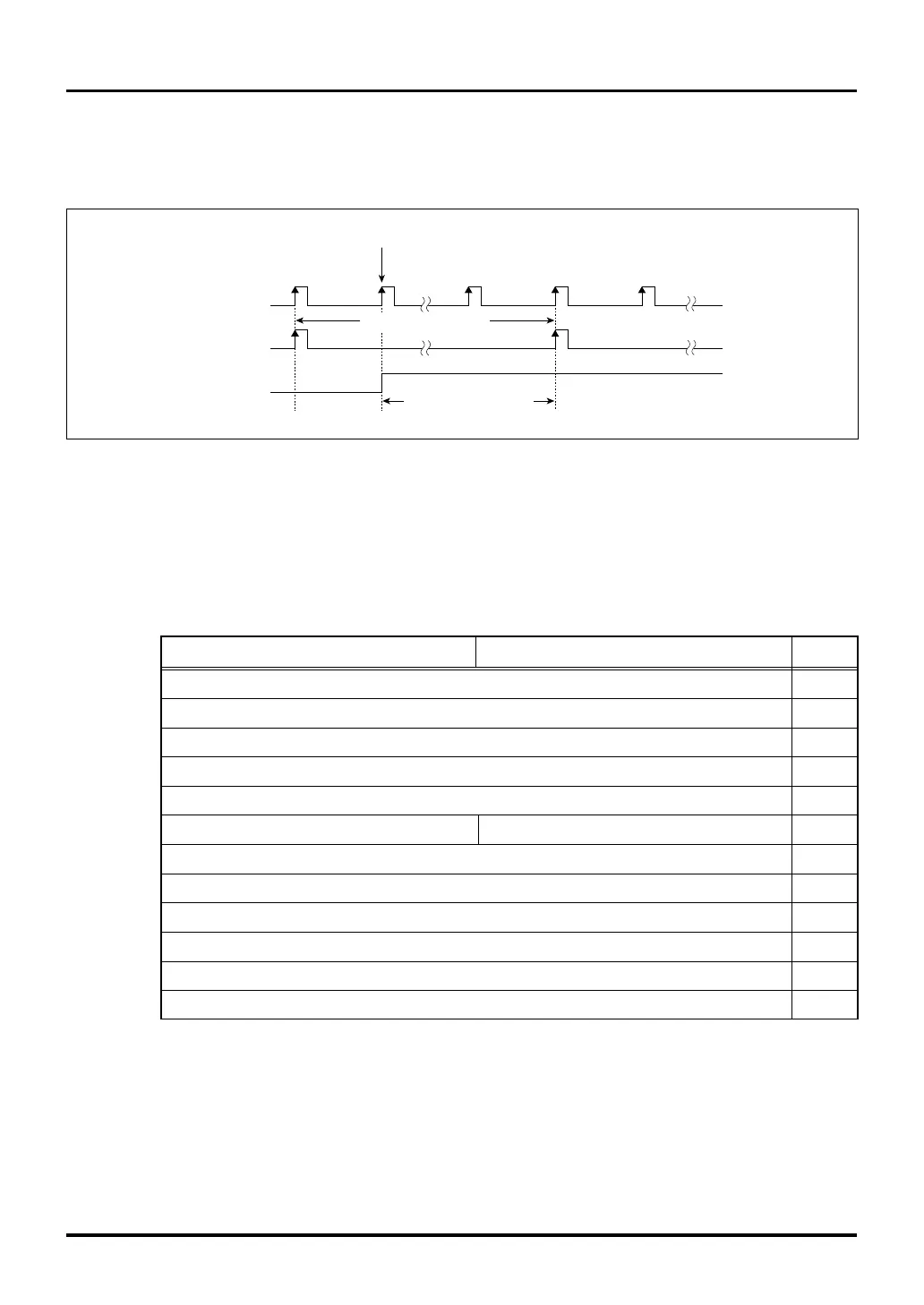
<Count clock-dependent delay>
• Because the timer operates synchronously with the count clock, there is a count clock-dependent delay
from when the timer is enabled till when it actually starts operating.
Figure 10.5.2 Count Clock-Dependent Delay
BCLK
Count clock
Enable
Count clock period
Count clock-dependent
delay
Write to the enable bit
|

 Loading...


