1-8
1
OVERVIEW
32180 Group User’s Manual (Rev.1.0)
1.3 Pin Functions
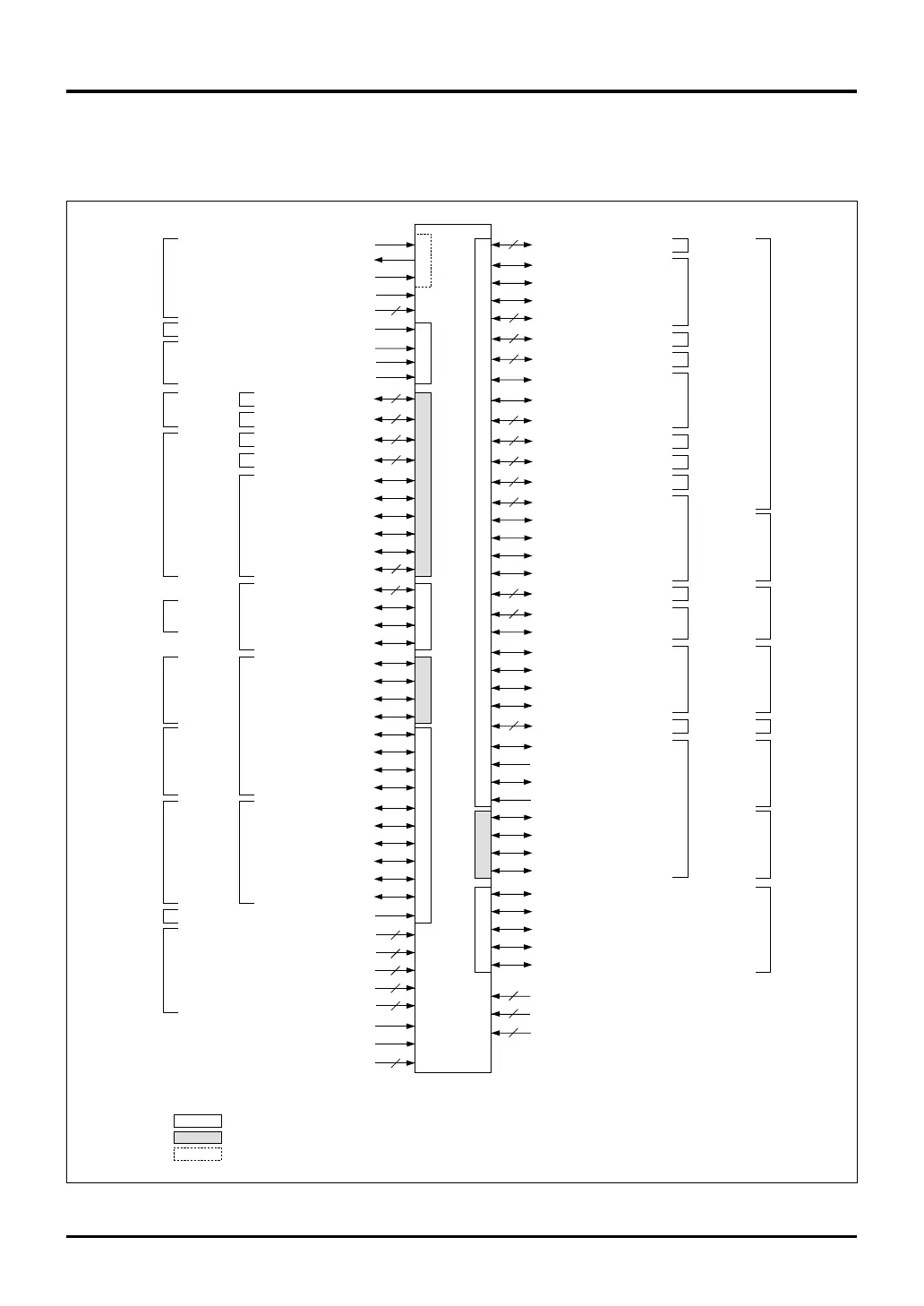
Figure 1.3.1 Pin Function Diagram
1.3 Pin Functions
Figure 1.3.1 shows the 32180’s pin function diagram. Pin functions are described in Table 1.3.1.
M32180F8VFP, M32180F8TFP
Port 15
Port 16
Port 13
Port 14
Port 12
Port 4
P45/CS1#
XIN
XOUT
VCNT
OSC-VCC
OSC-VSS
P70/BCLK/WR#
RESET#
MOD0
MOD1
FP
P220/CTX0
8
P221/CRX0
P224/A11/CS2#
P225/A12/CS3#
P222/CTX1
P223/CRX1
P226/CS2#
P227/CS3#
P150/TIN0-P157/TIN7
P160/TO21-P167/TO28
P180/TO29-P187/TO36
P190/TIN26-P196/TIN32
P210/TO37-P217/TO44
P197/TIN33/PWMOFF2
P130/TIN16/PWMOFF0
P131/TIN17/PWMOFF1
P132/TIN18-P137/TIN23
P140/TIN8-P147/TIN15
P124/TCLK0-P127/TCLK3
P93/TO16-P97/TO20
P100/TO8
P101/TO9/TXD3
P102/TO10/CTX1
P103/TO11-P107/TO15
P110/TO0-P117/TO7
AD1IN0-AD1IN15
AD0IN0-AD0IN15
AVCC0, AVCC1
AVSS0, AVSS1
VREF0, VREF1
P61-P63
P65/SCLKI4/SCLKO4
P66/SCLKI5/SCLKO5
P67
SBI#
VCCE
EXCVCC
VSS
P44/CS0#
P43/RD#
P42/BHW#/BHE#
P41/BLW#/BLE#
P71/WAIT#
P72/HREQ#
P73/HACK#
P20/A23-P27/A30
P30/A15-P37/A22
P46/A13, P47/A14
P00/DB0-P07/DB7
P10/DB8-P17/DB15
P82/TXD0
P83/RXD0
P84/SCLKI0/SCLKO0
P85/TXD1
P86/RXD1
P87/SCLKI1/SCLKO1
P174/TXD2
P175/RXD2
P172/TIN24, P173/TIN25
P176/TXD3
P177/RXD3
P200/TXD4
P201/RXD4
P202/TXD5
P203/RXD5
P74/RTDTXD
P75/RTDRXD
P76/RTDACK
P77/RTDCLK
JTMS
JTCK
JTRST
JTDO
JTDI
VDDE
EXCVDD
VCC-BUS
Bus control
Bus control
Address bus
Address bus
Bus control
Data bus
Serial I/O
Serial I/O
Serial I/O
Serial I/O
Serial I/O
RTD
Port 2
Port 3
Port 21
Port 22
Port 0
Port 1
Port 17
Port 18
Port 19
Port 20
Port 7
Port 8
JTAG
Port 11
Port 10
Port 9
Multijunction
timer
Multijunction
timer
Multijunction
timer
Clock
Reset
Mode
CAN
CAN
A-D converter
Interrupt
controller
Port 6
8
8
8
2
5
5
8
4
6
8
8
8
2
8
7
8
13
7
2
2
3
16
16
2
2
2
4
Notes: • The symbol "#" suffixed to the pin (or signal) names means that the pins (or signals) are active-low.
• : Operates with the VCCE power supply.
: Operates with the VCC-BUS power supply.
: Operates with the OSC-VCC power supply.
VCCE
VCCE
VCC-BUSVCCE
VCC-BUSVCC-BUSVCCE
VCC-BUS
VCCE
VCCE OSC-VCC
OSC-VCC

 Loading...


