18
18-3
OSCILLATOR CIRCUIT
32180 Group User's Manual (Rev.1.0)
18.1 Oscillator Circuit
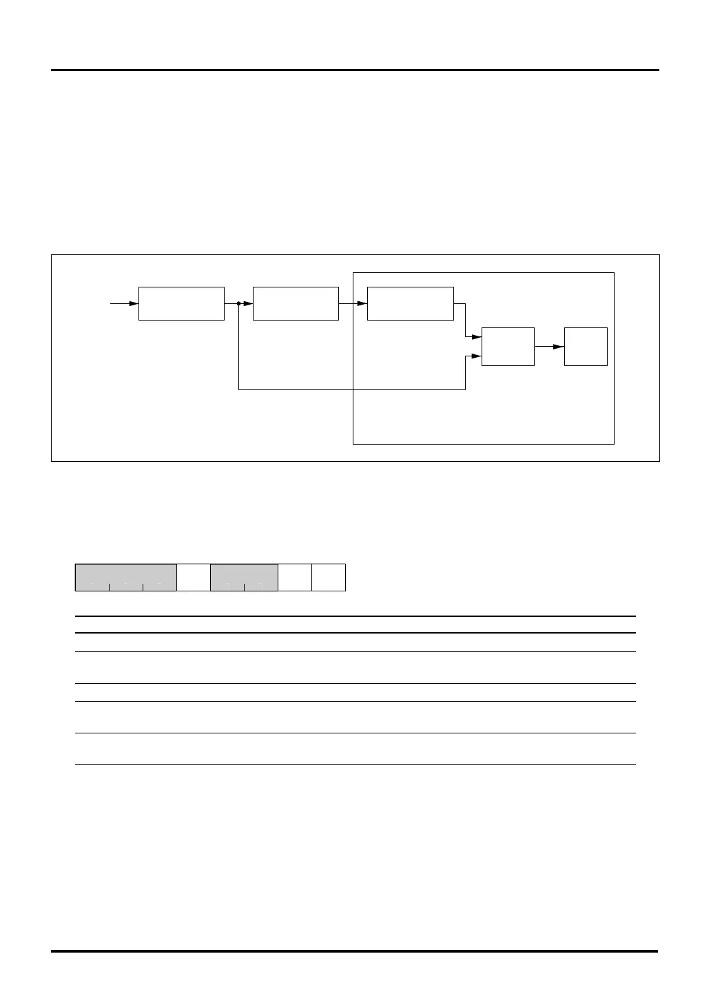
18.1.2 XIN Oscillation Stoppage Detection Circuit
The M32R/ECU contains a detection circuit to find whether oscillation input to the PLL circuit has stopped. The
PLL circuit has a characteristic that in the absence of the reference oscillation input, it oscillates with the fre-
quency of its normal mode of vibration.
The XIN oscillation input is sampled at the multiply-by-n frequency of the PLL circuit and when the XIN oscillation
is found to be at the same level, the XSTAT bit is set. Because the CPU continues operating with the PLL circuit’s
natural frequency even when the XIN oscillation has stopped, error handling for the stoppage of XIN oscillation
can be accomplished by inspecting XSTAT in software.
Figure 18.1.2 Block Diagram of the XIN Oscillation Stoppage Detection Circuit
Port Input Special Function Control Register (PICNT) <Address: H’0080 0745>
9 1011121314b15b8
PIEN0PISELXSTA
00
<After reset: H’00>
b Bit Name Function R W
8–10 No function assigned. Fix to "0". 0 0
11 XSTAT 0: XIN oscillating R (Note1)
XIN oscillation status bit 1: XIN inactive
12–13 No function assigned. Fix to "0". 0 0
14 PISEL 0: Content of port output latch R W
Port input data select bit 1: Port pin level
15 PIEN0 0: Disable input R W
Port input enable bit 1: Enable input
Note 1: Only writing "0" is effective. Writing "1" has no effect; the bit retains the value it had before the write.
For details about the function of the port input data select bit (PISEL) and port input enable bit (PIEN0), see Section
8.3.5, “Port Input Special Function Control Register.”
Determination
circuit
Oscillator
circuit
PLL circuit Counter
XIN
XS TAT
flag
XIN oscillation stoppage detection circuit

 Loading...


