10-117
10
10.4 TIO (Input/Output-Related 16-Bit Timer)
MULTIJUNCTION TIMERS
32180 Group User’s Manual (Rev.1.0)
Count clock
Counter
H'FFFF
H'0000
Enabled
(by writing to the enable bit
or by external input)
F/F output
Underflow
(first time)
TIO interrupt request
due to underflow
Enable bit
Note: • This diagram does not show detailed timing information.
Reload 0 register
H'A000
Underflow
(second time)
Count down from
the reload 1
register set value
H'(C000-1)
H'(A000-1)
Reload 1 register H'C000
Count down from
the reload 1
register set value
H'A000
PWM output period
H'C000
H'A000
Undefined
value
Count down from
the reload 0
register set value
Data inverted by
underflow
Data inverted by
enable
Data inverted by
underflow
H'(A000-1)
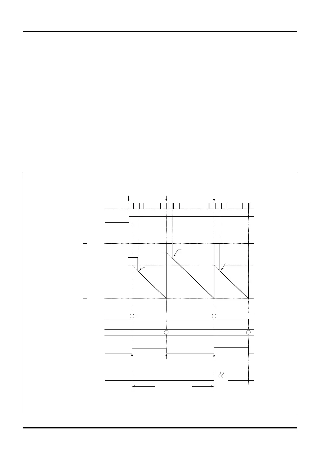
Figure 10.4.9 Typical Operation in PWM Output Mode
10.4.11 Operation in TIO PWM Output Mode
(1) Outline of TIO PWM output mode
In PWM output mode, the timer uses two reload registers to generate a waveform with a given duty cycle.
When the timer is enabled (by writing to the enable bit in software or by external input) after setting the initial
values in the reload 0 and reload 1 registers, the counter is loaded with the reload 0 register value and starts
counting down synchronously with the count clock. The first time the counter underflows, it is loaded with the
reload 1 register value and continues counting. Thereafter, the counter is loaded with the reload 0 and reload
1 register values alternately each time an underflow occurs. The (reload 0 register set value + 1) and (reload
1 register set value + 1) respectively are effective as count values. The timer stops at the same time count is
disabled by writing to the enable bit (and not in synchronism with PWM output period).
The F/F output waveform in PWM output mode is inverted (F/F output level changes from low to high or vice
versa) when the counter starts counting and each time it underflows. An interrupt request can be generated
when the counter underflows every other time (second time, fourth time and so on) after being enabled.
Note that TIO’s PWM output mode does not have the count correction function.

 Loading...


