11
11-6
A-D Converters
32180 Group User's Manual (Rev.1.0)
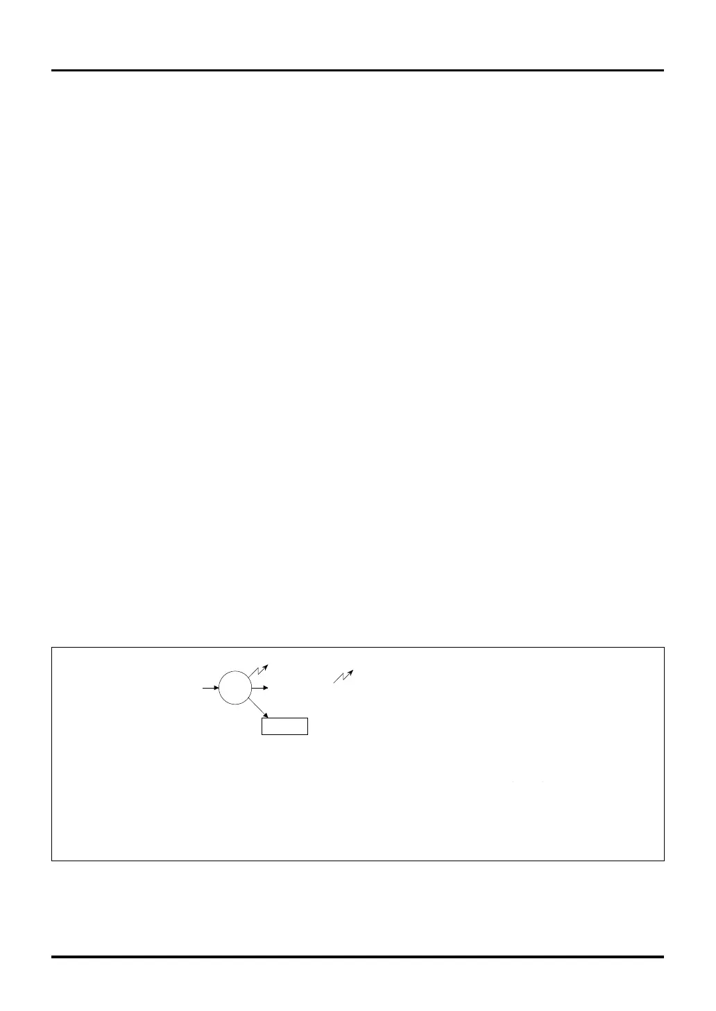
Figure 11.1.3 Operation in Single Mode (A-D Conversion)
A-D conversion interrupt or DMA transfer request
Note 1: A-D0 conversion start: Software trigger → Started by setting the A-D0 conversion start bit to "1"
Hardware trigger → Started by input event bus 3, input event bus 2,
output event bus 3 or TIN23S signal input
A-D1 conversion start: Software trigger → Started by setting the A-D1 conversion start bit to "1"
Hardware trigger → Started by input event bus 3, input event bus 2,
TID1_udf/ovf or TIN23S signal input
ANiINn
Completed
ADiDTn
10-bit A-Di Data Register
Conversion starts
(Note 1)
i=0, 1
n=0–15
11.1.1 Conversion Modes
The A-D Converters have two conversion mode: “A-D Conversion mode” and “Comparator mode.”
(1) A-D Conversion Mode
In A-D conversion mode, the analog input voltage on a specified channel is A-D converted. There are two
operation modes for A-D conversion mode as will be described later.
In single mode, A-D conversion is performed on a channel selected by the A-D Single Mode Register 1
analog input pin select bit.
In scan mode, A-D conversion is performed on channels selected by A-D Scan Mode Register 1 according to
settings of A-D Scan Mode Register 0.
The conversion result is stored in each channel’s corresponding 10-bit A-D Data Register. There is also an 8-
bit A-D Data Register for each channel, from which 8-bit A-D conversion results can be read out.
An A-D conversion interrupt or DMA transfer request can be generated when A-D conversion in single mode
is completed, as well as when one cycle of scan loop in scan mode is completed.
(2) Comparator Mode
In comparator mode, the analog input voltage on a specified channel is “comparated” (compared) with the succes-
sive approximation register value, and the result (relative magnitude of two values) is returned to a flag.
The channel to be comparated is selected using the A-D Single Mode Register 1 analog input pin select bit.
The result of comparate operation is flagged ("0" or "1") by setting or resetting the A-D Comparate Data
Register bit that corresponds to the selected channel.
An A-D conversion interrupt or DMA transfer request can be generated when comparate operation is completed.
11.1.2 Operation Modes
There are two operation modes for the A-D Converter: “Single mode” and “Scan mode.” When comparator mode
is selected as A-D conversion mode, only single mode can be used.
(1) Single Mode
In single mode, the analog input voltage on one selected channel is A-D converted or comparated once. An A-D conver-
sion interrupt or DMA transfer request can be generated when A-D conversion or comparate operation is completed.
11.1 Outline of A-D Converters

 Loading...


