10
10-91
MULTIJUNCTION TIMERS
10.3 TOP (Output-Related 16-Bit Timer)
32180 Group User’s Manual (Rev.1.0)
10.3.11 Operation in TOP Continuous Output Mode (without Correction Function)
(1) Outline of TOP continuous output mode
In continuous output mode, the timer counts down starting from the set value of the counter and when the
counter underflows, it is loaded with the reload register value. Thereafter, this operation is repeated each
time the counter underflows, thus generating consecutive pulses whose waveform is inverted in width of
(reload register set value + 1).
When the timer is enabled (by writing to the enable bit in software or by external input) after setting the
counter and reload register, it starts counting down from the counter’s set value synchronously with the count
clock and when the minimum count is reached, generates an underflow. This underflow causes the counter
to be loaded with the content of the reload register and start counting over again. Thereafter, this operation is
repeated each time an underflow occurs. To stop the counter, disable count by writing to the enable bit in
software.
The F/F output waveform in continuous output mode is inverted (F/F output level changes from low to high or
vice versa) at startup and upon underflow, generating a waveform of consecutive pulses until the timer stops
counting. An interrupt request can be generated each time the counter underflows.
The (counter set value + 1) and (reload register set value + 1) are effective as count values.
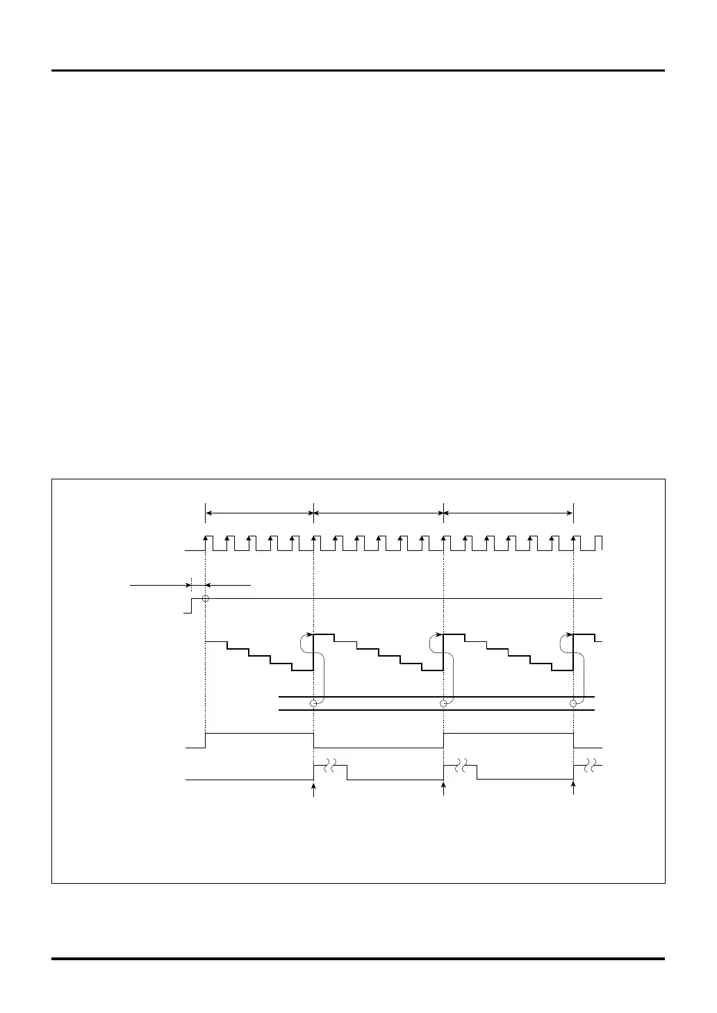
For example, if the initial counter value is 4 and the initial reload register value is 5, then the timer operates as
shown below.
Figure 10.3.17 Example of Counting in TOP Continuous Output Mode
(4)
3
2
1
1234
5
(Note 1)
F/F output
0
3
2
1
0
4
(5)
(Note 2)
3
2
1
0
(5)
(5)
4
5
123456123456
Count clock
dependent delay
Enable
Reload
register
Counter
Interrupt request
Count clock
Underflow
Note 1: What actually is seen in the cycle immediately after enable is the previous counter value, and not 4.
Note 2: What actually is seen in the cycle immediately after reload is H'FFFF (underflow value), and not 5.
Note: • This diagram does not show detailed timing information.
Underflow Underflow
(Note 2) (Note 2)
Count value = 5 Count value = 6 Count value = 6

 Loading...


