11
11-18
A-D Converters
32180 Group User's Manual (Rev.1.0)
11.2 A-D Converter Related Registers
11.2.2 A-D Single Mode Registers 1
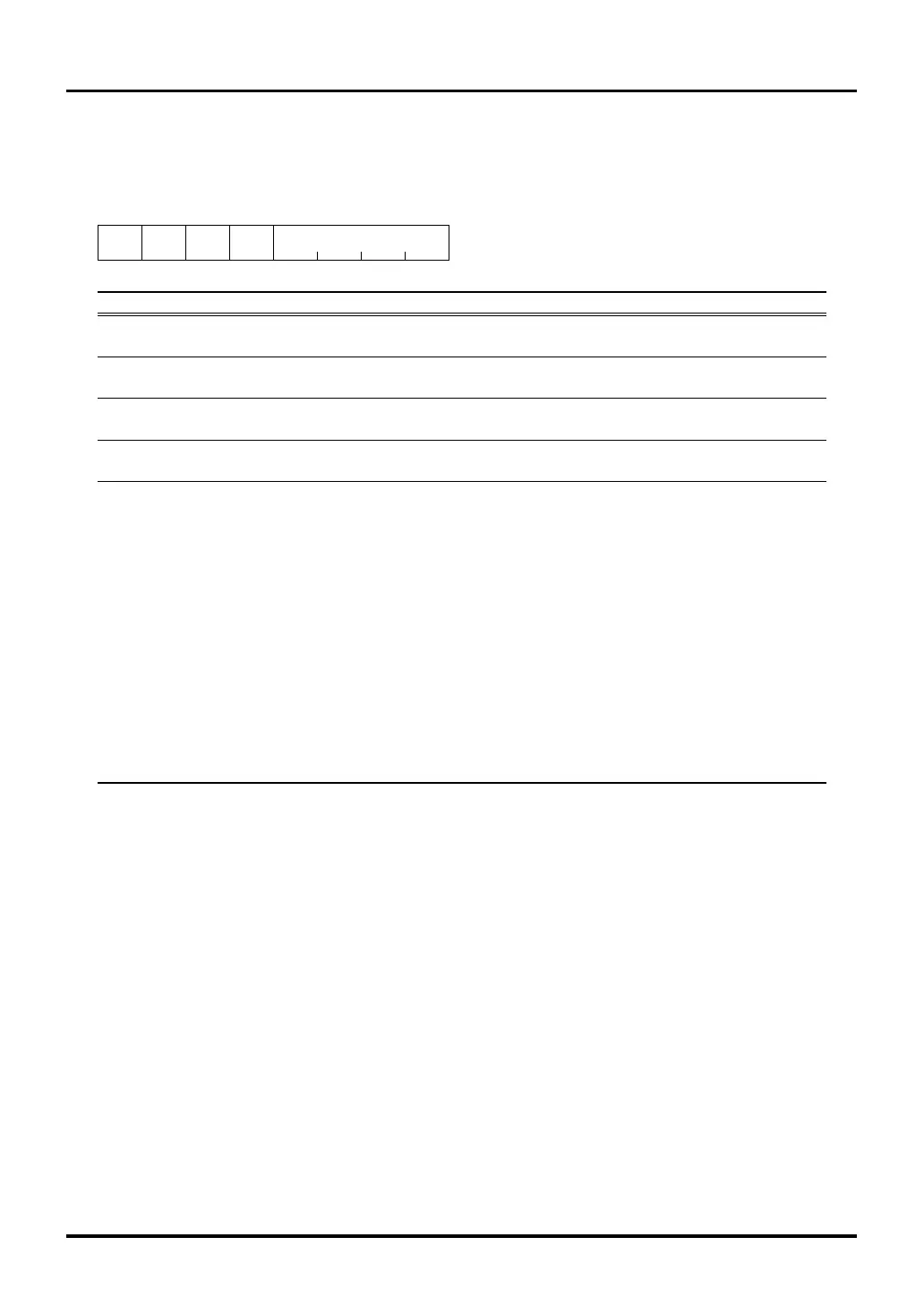
A-D0 Single Mode Register 1 (AD0SIM1) <Address: H’0080 0081>
A-D1 Single Mode Register 1 (AD1SIM1) <Address: H’0080 0A81>
9 1011121314b15b8
ADSMSL ADSSPD ADSSHSL
ANSEL
00000000
ADSSHSPD
<After reset: H’00>
b Bit Name Function R W
8 ADSMSL 0: A-D conversion mode R W
A-D conversion mode select bit 1: Comparator mode
9 ADSSPD (Note 1) 0: Normal speed R W
A-D conversion speed select bit 1: Double speed
10 ADSSHSL 0: Disable sample-and-hold R W
A-D conversion method select bit 1: Enable sample-and-hold
11 ADSSHSPD (Note 2) 0: Normal sample-and-hold R W
A-D sample-and-hold conversion speed select bit 1: Fast sample-and-hold
12–15 ANSEL 0000 : Select ADiIN0 (i = 0, 1) R W
A-D analog input pin select bit 0001 : Select ADiIN1
0010 : Select ADiIN2
0011 : Select ADiIN3
0100 : Select ADiIN4
0101 : Select ADiIN5
0110 : Select ADiIN6
0111 : Select ADiIN7
1000 : Select ADiIN8
1001 : Select ADiIN9
1010 : Select ADiIN10
1011 : Select ADiIN11
1100 : Select ADiIN12
1101 : Select ADiIN13
1110 : Select ADiIN14
1111 : Select ADiIN15
Note 1: The A-D conversion speed is determined by a combination of ADSSPD, ADSSHSL and ADSSHSPD bits and the A-D
Conversion Speed Control Register ADCVSD bit.
Note 2: Setting of this bit is effective when the sample-and-hold function is enabled by ADSSHSL bit.
A-D Single Mode Registers 1 are used to select operation mode, conversion speed and analog input pins when
the A-D Converter is operating in single mode.

 Loading...


