20
20-6
POWER SUPPLY CIRCUIT
32180 Group User's Manual (Rev.1.0)
20.3 Power-Off Sequence
20.3.2 Power-Off Sequence when Using RAM Backup
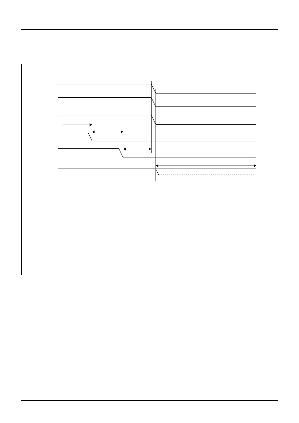
The diagram below shows a turn-off sequence of the power supply (5.0 V or 3.3 V) when using RAM backup.
VCCE,
VCC-BUS,
OSC-VCC
AVCC
VREF
RESET#
VDDE
P72/HREQ#
3V
(Note 1)
(Note 2)
(Note 3)
(Note 4)
Note 1: Pull the HREQ# input pin low to halt the CPU at the end of the bus cycle.
Or disable RAM access in software. P72 can be used as HREQ# irrespective of the operation mode.
However, HREQ# must be selected with the Port Operation Mode Register for P72.
Note 2: Pull the RESET# input pin low while the CPU is halted or RAM access is disabled.
Note 3: Wait until the RESET# pin goes low before turning the power supply off.
Note 4: Lower the VDDE voltage from 5.0 V to 3.0 V as necessary.
Notes: • Power-off limitations
VCCE = OCS-VCC
VDDE ≥ VCCE, OSC-VCC
• However, if the above power-off limitations cannot be met, sufficient evaluation must be made during system design
in order to ensure that no power will be applied to the microcomputer with a potential difference of 1 V or more.
For potential differences 0 V to 0.6 V, there is almost no in-flow current. The amount of in-flow current begins to increase
when the potential difference exceeds 0.6 V.
0V
0V
0V
0V
0V
Figure 20.3.2 Power-Off Sequence when Using RAM Backup (VCCE = 5.0 V or 3.3 V)

 Loading...


