16
16-6
WAIT CONTROLLER
32180 Group User’s Manual (Rev.1.0)
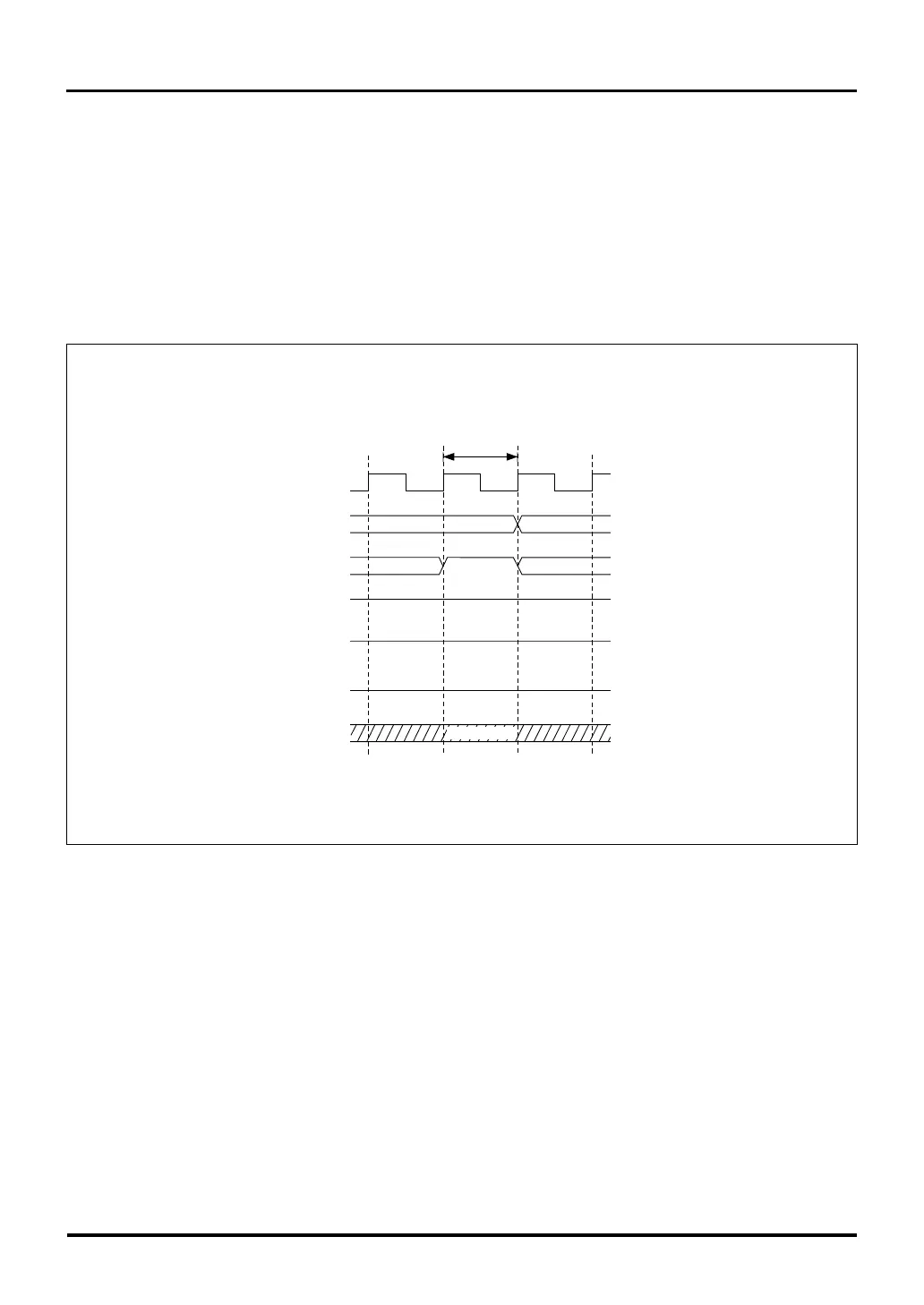
Figure 16.3.1 Internal Bus Access during Bus Free State
16.3 Typical Operation of the Wait Controller
The following shows a typical operation of the Wait Controller. The Wait Controller can control bus access in zero
to 7 cycles. If more access cycles than that are needed, use the WAIT function in combination with the Wait
Controller.
(1) When the Bus Mode Control Register = 0
External read/write operations are performed using the address bus, data bus and the signals CS0#–CS3#,
RD#, BHW#, BLW#, WAIT# and BCLK.
16.3 Typical Operation of the Wait Controller
Bus free state
Internal bus access
"H"
BCLK
A11–A30
CS0#–CS3#
BHW#, BLW#
DB0–DB15
WAIT#
RD#
"H"
Hi-z
Note 1: For details about the Bus Mode Control Register, see Section 15.2.3, "Bus Mode Control Register."
Note: • Hi-Z denotes a high-impedance state.
(Don't Care)
Bus Mode Control Register (Note 1)
BUSMOD bit = 0 (WR signal separated)

 Loading...


