16
16-4
WAIT CONTROLLER
32180 Group User’s Manual (Rev.1.0)
16.2 Wait Controller Related Registers
Shown below is a Wait Controller related register map.
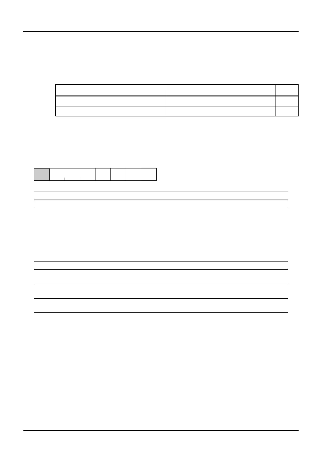
Wait Controller Related Register Map
Address +0 address +1 address See
b0 b7 b8 b15 pages
H'0080 0180 CS0 Area Wait Control Register CS1 Area Wait Control Register 16-4
(CS0WTCR) (CS1WTCR)
H'0080 0182 CS2 Area Wait Control Register CS3 Area Wait Control Register 16-4
(CS2WTCR) (CS3WTCR)
16.2.1 CS Area Wait Control Registers
CS0 Area Wait Control Register (CS0WTCR) <Address: H’0080 0180>
123456b7b0
WTCSEL (Note 3) SWAIT RECOV IDLE
1111111
<After reset: H’7F>
b Bit Name Function R W
0 No function assigned. Fix to "0". 00
1–3 WTCSEL 000: 0 wait state (Note 1) R W
CSn block wait states select bit 001: 1 wait state (Note 2)
010: 2 wait state
011: 3 wait state
100: 4 wait state
101: 5 wait state
110: 6 wait state
111: 7 wait state
4 When using external bus, set this bit to "0". (Note 3) R W
5 SWAIT 0: No strobe wait R W
Strobe signal wait bit 1: Strobe wait added
6 RECOV 0: No recovery cycle R W
Recovery cycle addition bit 1: Recovery cycle added
7 IDLE 0: No post-read idle cycle R W
Post-read idle cycle addition bit 1: Post-read idle cycle added
Note 1: When zero wait state is selected, wait states inserted by external WAIT input are not accepted. For zero wait state also,
make sure the SWAIT, RECOV and IDLE bits all are set to "0". Otherwise, device operation cannot be guaranteed.
Note 2: When one wait state is selected, do not set SWAIT bit = 1. Otherwise, device operation cannot be guaranteed.
Note 3: When using an external bus, set this bit to "0".
If a read cycle is followed immediately by a write cycle, one idle cycle is inserted unless RECOV bit = 1 and IDLE
bit = 0. Table 16.2.1 shows the relationship between RECOV bit and IDLE bit settings and the number of idle
cycles inserted after the bus cycle.
16.2 Wait Controller Related Registers

 Loading...


