15
15-17
EXTERNAL BUS INTERFACE
32180 Group User’s Manual (Rev.1.0)
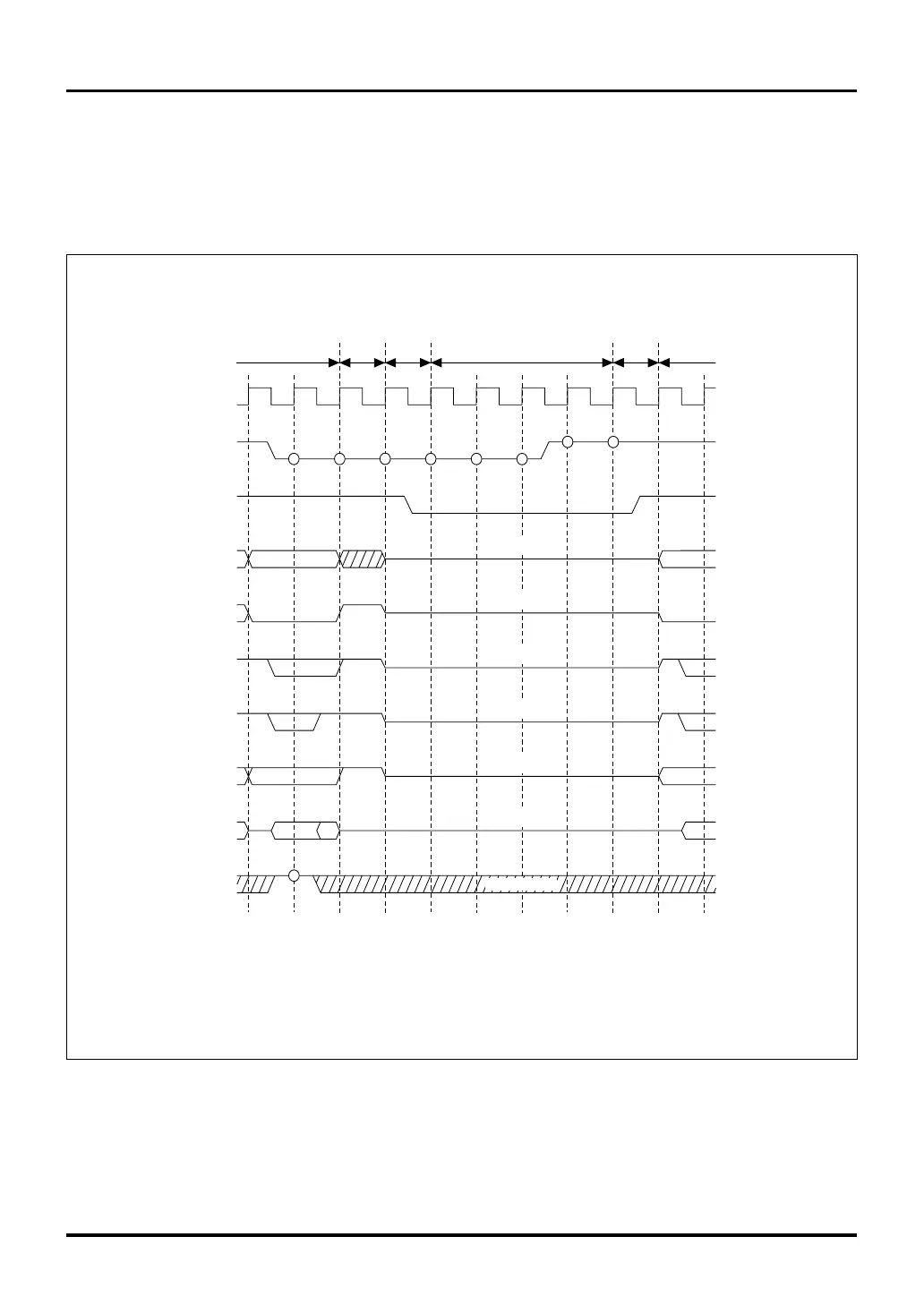
(2) When the Bus Mode Control Register = "1"
When the input signal on the HREQ# pin is pulled low and the hold request is accepted, the microcomputer
goes to a hold state and outputs a low from the HACK# pin. During hold state, all bus related pins are placed
in the high-impedance state, allowing data to be transferred on the system bus. To exit the hold state and
return to normal operating state, release the HREQ# signal back high.
Figure 15.4.2 Bus Arbitration Timing
DB0–DB15
BCLK
Note 1: For details about the Bus Mode Control Register, see Section 15.2.3, "Bus Mode Control Register."
Notes: • Circles in the above diagram denote the sampling timing.
• Hi-Z denotes a high-impedance state.
• Idle cycles are inserted only when a hold state is entered immediately following an external read access.
HREQ#
HACK#
A11–A30
CS0#–CS3#
RD#
BHW#, BLW#
WAIT#
Hi-Z
(Don't Care)
Hi-Z
Hi-Z
Hi-Z
Hi-Z
Hi-Z
WR#
Bus Mode Control Register (Note 1)
BUSMOD bit = 1 (byte enable separated)
Bus cycle
Idle
Go to
hold state
Hold state
Return
Next
bus cycle
15.4 Bus Arbitration

 Loading...


